

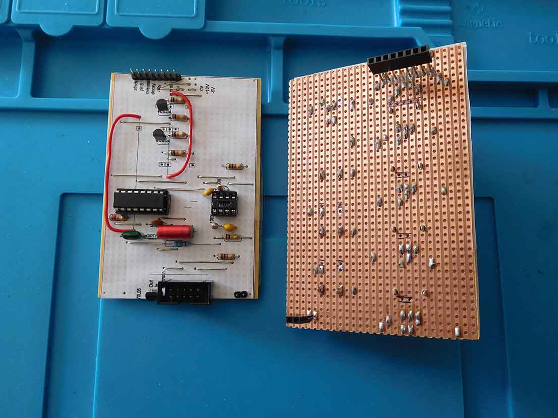
Stripboard CEM3310 envelope generator
This stripboard CEM3310 envelope generator was inspired by the envelope generator on the Sequential Circuits Pro 1 synthesizer.
If you are interested in building this circuit on a breadboard first check out my post Breadboard envelope generator.
This was something I intended to do for years but never got around to it. However, the Covid lockdown provided the ideal opportunity. I was lucky enough to own a Pro 1 amongst other synthesizers in the past. I used it quite a lot and at the same time, I had an Oxford synthesizer company OSCar.
Along with the Pro 1, these were my main 2 mono synths. They sounded completely different to each other and one thing I noticed was that even though the Oscar is a fantastic synthesizer and definitely one of my favourites however the envelope generator is not that quick.
This could be because it’s generated in software. I guess you really only notice it when comparing it next to another synth.
The Stripboard CEM3310 is just one of my synthesiser Stripboard projects. There is also the Stripboard CEM3320 voltage-controlled filter. This is also based on the Pro 1 design.
Next is the CEM3340 voltage-controlled oscillator. Also similar to the Pro 1 oscillator circuit. To control all of these is the Stripboard MIDI to CV converter.
If you have even the slightest interest in things stripboard related then check out my post, Stripboards – the complete guide. I’m sure you’ll pick up at least one tip to save you either time or money!
Electronics and music maker Spectrum synthesizer
I also built a kit synth at the same time. This was originally a magazine project, the Electronics and music maker Spectrum synthesizer. It also used the Curtis electro-music range of CEM ICs like the Sequential Circuits Pro 1 but was a little more versatile.

The filter on the Spectrum could be switched to low pass, band pass as well as high pass. The oscillator synchronisation was also a lot more advanced. If you are interested in the oscillator synchronisation method check out my post here. I’m going to be doing some experiments with it and trying to implement something like it. I’m also going to try to take it a bit further.
The envelopes on the Spectrum didn’t sound as good as the Pro 1 despite using the same CEM3310 ICs. So I decided to breadboard up some CEM3310 circuits and try and find out how and why the differences occurred and what made them.
I actually used the CEM3310 equivalent, the AS3310.

Stripboard CEM3310 envelope generator circuit similarities
There were plenty of similarities between a lot of the CEM3310 circuits and the datasheet. There were a few things that I didn’t think would make much difference however as I was using breadboard it was relatively easy to test them out to make sure.

Most modern CEM3310 circuits don’t use a -5 volt supply instead they use a 750-ohm resistor to pin 6 and connect that to -15V or -12V. I used a 79L05 regulator on the breadboard and checked it out against the 750-ohm resistor and -5V method. I couldn’t detect any difference using either technique with ears or an oscilloscope.
Timing capacitors
Another of the things I tried was looking at the values of the capacitors that go to pins 1 and 8. I used the automatic component tester to measure exact values as they can vary quite a lot. Changing the values slightly again didn’t make much difference. The values I finished with were 39nF and 22nF. This is pretty much the datasheet standard values.
The resistor between pin 2 and 10 is marked as 24K on the datasheet but I saw a Frequency Central design which is based on the Pro 1 circuit of the envelope generator and they had used a 22K. I tried both but again I couldn’t detect any difference.
Next, I moved on to the triggering. The Pro 1 doesn’t have much circuitry before the gate and trigger inputs to the CEM3310. I did a few experiments testing the gate and trigger. I tried gating directly and then using a couple of transistors.
Again this didn’t make any difference so I used the transistors to act as an extra buffer protecting the CEM3310. Similarly, I used a dual op-amp on the output to buffer the signal and invert it to give more options in its use.
Stripboard CEM3310 envelope generator circuit differences
The only other area and the one that I believe makes the difference in creating the punchy sound are the connections to the CEM3310 attack, decay, sustain and release inputs.
One of the circuits uses 100K linear variable resistors with the attack, decay and release going to 12V at one end and 0V at the other. The central connection goes through a 10K resistor and then to the three pins 15,12 and 13. These also have 470R resistors connected to each pin and to 0V. The sustain variable resistor has one side of the 100K linear pot connected to 0V and the other side to pin 3 with its central connection going directly to pin 9.
This is where the Pro 1 envelope generator circuit differs.

It still uses 100k linear variable resistors for the attack, decay and release however in this case each central connection goes straight to pins 15, 12 and 13. One side connects to 0V while the other sides connect to a large value resistor. This then connects then to the -5V that the Pro 1 uses to connect to pin 6 instead of using a 750 Ohm resistor.
The Pro 1 circuit uses a 1.8M for attack and release and a 2M resistor for the decay. The sustain has a 200k resistor connecting to +15V and then to the 100K variable resistor with the other end going to 0V and the central connection going directly to pin 9.
I believe this to be the main difference in the Pro 1 circuit. The Frequency Central design uses 2M resistors for all three, attack, decay and release. Altering the attack to 1.8M made no noticeable difference.
Stripboard CEM3310 envelope generator layout

On the layout above I had to use a couple of insulated wires as links. These are shown in red.
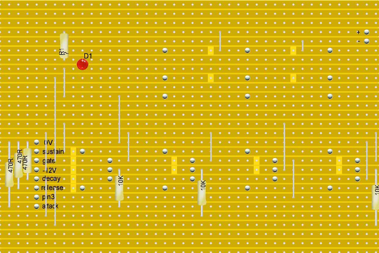
In laying this out on the stripboard I’ve used my usual methods. The Eurorack socket for the power and a single inline (SIL) connector. This plugs into the variable resistor and socket board. This makes sense to have some of the other components mounted on it as well like the resistors around the variable resistors. These can then be directly connected to the relevant pins on the CEM3310.
As you can see I’ve made this design similar to the Eurorack format. This makes using and casing them a lot easier. For more information about how exactly I’ve done this, check out my article on using Stripboards to build synthesiser Eurorack modules.
You will also find extra information about Stripboard layout and construction in my Stripboard tips guide.
To make construction easier I use the Lochmaster software as I find it easier to make a layout with it. You can move components around without resorting to an eraser and produce calibrated size and flipped printouts so you can cut the tracks in the correct places and put the components in the correct holes without having to count.
These are two of the main reasons why stripboard layouts don’t work by the way.
Tracks cut in the wrong place or components were put in the wrong holes.
Bridging two tracks together while soldering.

A final thought on the stripboard CEM3310 envelope generator
If you’re looking to add an envelope generator or two to your set up the CEM3310 or its equivalents means you can achieve a very good envelope generator at a very low cost. You don’t need many other components either so it’s not that time-consuming to build.
As you clearly have an interest in building synthesiser projects, I’m sure you’ll be interested in my Breadboard synthesiser project. This was the biggest thing I’d ever built on a breadboard and It sounds and works quite like the Sequential Circuits Pro 1.
Information
The Sequential Circuits Pro 1 was used for lots of the sounds on the Yazoo – Upstairs at Eric’s album.
Vince Clarke says it is his favourite synthesiser of all time.

“Hi, I’m Graham Moore and I’ve been building electronic projects since I was 12. I had a fascination for old radios and taking them to pieces but when my Nan bought me an electric soldering iron, I realised with a few components I could build stuff.
Learning to solder opened up many doors for me as electronics also became a career. I hope you get as much from it as i did”.
Hide Ads for Premium Members
[quads_disable_ads_form]
555 monostable calculator

555 monostable calculator Download the 555 monostable calculator to easily work out the time from the components. Once you have downloaded the spreadsheet, all you have to do is input…
555 astable calculator

555 astable calculator Click further down the page for a downloadable 555 astable calculator. If you’ve joined this guide from the 555 operating modes page or even if you haven’t,…
555 timer modes

555 timer modes The 555 timer has 3 main modes of operation. These three 555 timer modes are astable, monostable and bistable. You can achieve each of the modes by…
How to test a 555 timer

How to test a 555 timer This guide will show you how to test a 555 timer. I’ve covered testing many types of electronic components before and this tends to…
Capacitor value codes

Capacitor value codes Capacitor value codes are often used to indicate the value of a capacitor. Whereas resistors have usually stuck to a standard colour code (well standard-ish as it…
Lite windows with DAWs

Lite Windows with DAWs I wondered how much performance boost I’d get using Lite Windows with DAWs. The test results were shocking! A few years ago I decided to use…
How to connect Kodi to a network drive

How to connect Kodi to a network drive If you need to know how to connect Kodi to a network drive, it will depend on your particular network drive. I’m…
Can you solder without flux?

Can you solder without flux? The simple answer to can you solder without flux is no. The good news is that if you have got some solder it’s more than…