

How to build a Breadboard envelope generator
This breadboard envelope generator can be built on its own or as part of my complete MIDI breadboard synthesiser project.
I used to think an envelope generator was something the post office used, It’s not, it’s something very useful if not essential when it comes to synthesizers.
This breadboard envelope generator uses the Curtis Electromusic CEM3310 or an equivalent. I actually used an equivalent which was the AS3310.


What is an envelope generator?
It’s generally used to re-create the attack, decay, sustain and release portions of a sound envelope. That is where the ADSR comes from and this is an ADSR envelope generator. There are other types but this one is an ADSR.
Once triggered by a gate or trigger signal it generates a voltage that starts at 0V and rises to its maximum, this is the attack. The attack control sets the time it takes. Once this is reached it progresses to the decay portion. This time is set by the decay control, where the voltage goes down to the sustain level.
The sustain control sets this. It stays at this level until the gate signal ends. This is usually when you release a key on the keyboard. When the gate ends the envelope progresses to its release time. Unsurprisingly by now, it is set by the release control. The voltage decays from the sustain level back to 0V.
An envelope generator is used with a voltage-controlled amplifier to produce the volume effects described above.
I’ve actually put two envelope generators on the breadboard because firstly you can fit two on it and secondly you really need two at the very least in a synthesizer. One for the voltage controller amplifier and one for the voltage-controlled filter.

If you are building more complex breadboard layouts you’ll find it easier if you make your own links instead of using the pre-made links, for some other breadboard tips click here.

Breadboard envelope generator parts list
Resistors
You can use 5% tolerance carbon resistors if you want but I tend to only buy 1% metal film ones these days and use those throughout. It may seem overkill on some designs but they are that cheap for me and I use less storage space trying to keep two values of each sort.
10K resistors x 6
470R resistors x 6
750R resistors x 2
24K resistors x 2
Capacitors
I just used ceramic capacitors as I had them lying around.
22nF x 2
39nF x 2
1nF x 2
Variable resistors
8 x 100K linear variable resistors
Integrated circuits
2 x CEM3310 or equivalent, I used AS3310’s
Breadboard and wires
breadboard envelope generator construction
Firstly, and importantly do not connect the two red columns together on this project. Although I like to generally stick to the unwritten rule that they are usually connected together it made much more sense with this project that the left-hand (from the top) red column is used for the -12V.
Sometimes this has to happen and I guess it’s why they aren’t internally permanently connected.
If you are a beginner I’ve written an article “Breadboard tips” to help the beginner and sometimes the experts.
I’ve mentioned this before. I take the breadboard circuit to pieces and reassemble it by following the instructions listed below just to try to make sure there are no errors or omissions. However, you will learn more if you do a printout of the circuit and highlight the component and connection when you make it on the breadboard.
This way you will learn much more when it comes to laying out your own circuits. You’ll also be much more likely to spot any mistakes.
First, connect the short uninsulated tinned copper wire links.
1. Link 3e to 3f
2. Link 9e to 9f
3. Link 21e to 21f
4. Link 33e to 33f
6. Link 51e to 51f
7. Link 24j to 24Z (blue column)
8. Link 27j to y27y (red column)
9. Link 28i to i30i
10. Link 54j to 54Z (blue column)
11. Link 57j to 57Y (blue column)
12. Link 58i to 60i
13. Link 23d to 30d
14. Link 53d to 60d
15. Link 3a to 3w (red column)
16. Link 9a to 9w (red column)
17. Link 21a to 21w (red column)
18. Link 28a to 28x (blue column)
19. Link 31a to 31w (red column)
20. Link 33a to 33w (red column)
21. Link 39a to 39w (red column)
22. Link 51a to 51w (red column)
23. Link 58a to 58x (blue column)
24. Link 61a to 61w (red column)
Resistors
25. 10K resistor 2h to 6h
26. 10K resistor 8h to 12h
27. 10K resistor 20l to 25l
28. 10K resistor 32h to 36h
29. 10K resistor 38h to 42h
30. 10K resistor 50i to 55i
31. 470R resistor 25j to 25z (blue column)
32. 470R resistor 55j to 55z (blue column)
33. 470R resistor 6f to 7f
34. 470R resistor 12f to 13f
35. 470R resistor 36f to 37f
36. 470R resistor 42f to 43f
37. 24K resistor 30e to 30g
38. 24K resistor 60e to 60g
Also check out my post, Breadboards – the complete guide, for everything you need to know about breadboards.39. 750R resistor 27c to 31c
40. 750R resistor 57c to 61c
Capacitors
41. 22nF capacitor 29a to 29x (blue column)
42. 22nF capacitor 59a to 59x (blue column)
43. 39nF capacitor 22a to 22x (blue column)
44. 39nF capacitor 52a to 52x (blue column)
45. 1nF capacitor 25a to 26a
46. 1nF capacitor 55a to 56a

Next, connect up the blue wire links to get each variable resistor to connect a leg to 0V.
47. Blue wire link 1i to 4z (blue column)
48. Blue wire link 7i to 10z (blue column)
49. Blue wire link 13i to 16z (blue column)
50. Blue wire link 19i to 22z (blue column)
51. Blue wire link 31i to 35z (blue column)
52. Blue wire link 37i to 41z (blue column)
53. Blue wire link 43i to 47z (blue column)
54. Blue wire link 49i to 53z (blue column)
55. Next insert the variable resistors.
56. 100K linear variable resistor 1j, 2j and 3j
57. 100K linear variable resistor 7j, 8j and 9j
58. 100K linear variable resistor 13j, 14j and 15j
59. 100K linear variable resistor 19j, 20j and 21j
60. 100K linear variable resistor 31j, 32j and 33j
61. 100K linear variable resistor 37j, 38j and 39j
62. 100K linear variable resistor 43j, 44j and 45j
63. 100K linear variable resistor 49j, 50j and 51j
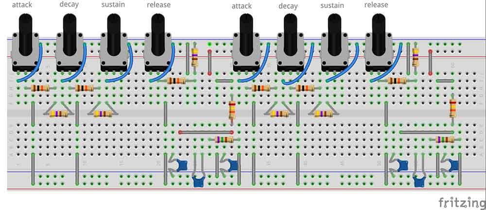
Finally, connect the insulated wiring:
64. White wire h14 to h29
65. White wire h44 to h59
66. White wire g12 to g26
67. White wire g42 to g56
68. Yellow wire g6 to g23
69. Yellow wire g36 to g53
70. Yellow wire f15 to c24
71. Yellow wire f45 to c54
Plug in the two CEM3310 or equivalent ICs one with pin 1 at e22 and the other with pin 1 at e52.
Link the two blue columns together but not the two reds!
The 0V connects to the blue column, the +12V connects to the red column on the right-hand side (from the top) and -12V to the red column on the left-hand side (from the top)
One envelope out is from b23 and the other is from b53.

The picture above is produced using breadboard design software. It’s a lot neater than the scraps of paper I used to scribble on.
The gate signal connects to c25 and c55.

Final thoughts on the breadboard envelope generator
If you have any trouble getting this project working check out my guide, Common Breadboard Mistakes.
When I put my oscilloscope on the output to check that the breadboard envelope generator and all the controls were working correctly I noticed that you can clearly see that the slopes are exponential and not linear. This is with the cheap DSO138 if you can’t afford much for an oscilloscope this is well worth getting!
If you want to make this project on stripboard, then have a look at my Building a Stripboard Envelope Generator article.

If you want to build a full synthesizer check out my article “Breadboard Synthesizer Project” here.
Finally, check out my post, Breadboards – the complete guide, for everything you need to know about breadboards.

“Hi, I’m Graham Moore and I’ve been building electronic projects since I was 12. I had a fascination for old radios and taking them to pieces but when my Nan bought me an electric soldering iron, I realised with a few components I could build stuff.
Learning to solder opened up many doors for me as electronics also became a career. I hope you get as much from it as i did”.
Breadboard design software

Breadboard design software tested and compared If you use breadboards, you might find breadboard design software helps with your building. Breadboards are tremendously useful for beginners who can’t solder…
Breadboard tips

Breadboard tips I learnt to use breadboards in a sort of trial-and-error method. There doesn’t seem to be much in the way of instructions on how to use a breadboard….
Best breadboard kit buyers guide

Best breadboard kit buyers guide In this “Best breadboard kit buyers guide”, I’ll attempt to point you in the direction of the kit that best suits you. Breadboard kits come…
Where to buy breadboards

Where to buy breadboards So if you’ve found this page that means you’ve probably decided you want to buy a solderless breadboard and you want to know where to buy…