

Breadboard tips
I learnt to use breadboards in a sort of trial-and-error method. There doesn’t seem to be much in the way of instructions on how to use a breadboard. I’ve put a few breadboard tips here that I wish I’d known when I started using them.

Breadboard tips – 1 preform and trim the components
I used to manually bend and trim the wire links and components. Then I just guessed and bent them to try to fit as well as I could get them. It wasn’t until I started to pre-form components that I realised how much quicker and accurate it was. No more guessing and bending it to try and fit. I also realised that I was cutting the component leads a little shorter than I should of.
You can plug a lead about 6mm into the breadboard and still have it lay flat. Have a look and see how thick the breadboards are and insert a piece of tinned copper. Pull it out and you’ll see how far it goes fully in.
It makes more sense to use the full distance to plug the components into. Firstly they are held in mechanically better and secondly, they will make a better electrical connection as there is more surface area in contact between the component lead and breadboard socket.
Always make sure that the component leads are clean. If they are not they won’t make a very good electrical connection and the circuit might not work at all or even worse work intermittently because of that connection. Secondly, you will dirty and damage the sockets in the breadboard potentially ruining it.
Information
The modern plastic breadboard in use today, with .1 inch spacing holes was patented in 1971 by Ronald Portugal.
Breadboard tips – 2 make a preform tool
At first, I was bending and pre-forming components around some objects that came to hand. Soon I came to the conclusion that I could make something much better.
I made a quick design in the Inkscape vector software. This was so that I could pre-form .3 inches up to 1.1 inches in steps. Making the design out of a 6mm thick material enables you to trim off against it to get the correct 6mm length legs. After using it for a while I can confirm that it really speeds up my breadboard prototype construction. In fact, I’ve become so reliant on it that I won’t build anything on a breadboard without it. It just takes too long trying to do it with long nose pliers and guessing.
One thing I will do in the future to make it even better is to drill a series of holes .1 inches apart for components that have legs that don’t need bending like radial electrolytic capacitors. You can push the component through the holes and trim the leads flush for the perfect breadboard length.
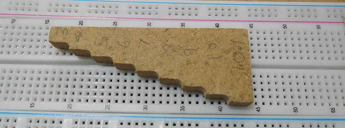
Apart from getting a better connection with 6mm length legs, you can reuse them in printed circuit boards afterwards as being slightly longer you have enough length for it to go through a PCB.
Breadboard tips – 3 Save the preformed links and components
Using the preforming tool you can keep the links and reuse them afterwards in your next project. You just need a small compartmentalised plastic box for the common sizes. You will mostly be using links of .2inch in .1inch steps up to .6inch. This will also make your building faster.
Breadboard tip – 4 Check power before you plug in ICs
Leave the DIL ICs until last and before you plug them in power up the breadboard and put a multimeter on the breadboard sockets where the ICs are going to plug in to make sure the IC power pins are going to get the correct voltage at the correct polarity. This will definitely save you a few ICs over the years if you get into the habit of doing this.
Breadboard tips – 5 Check the power rails
Look at the picture below, notice anything? Yes, the power rails are different, with the number “1” row to the left in both breadboards, one has the blue rail next to the number “60” and the other has the red rail next to the number “60”. Someone must have thought this wasn’t a good idea.

I bought a pack of three full-size and two half-size breadboards from Amazon and the half-size ones are different to the full-size ones. I would have thought that they would be the same. When you consider that these are used a lot by beginners it seems totally bizarre to me. So the tip is to check to see if your breadboards are the same as the diagram or picture that you are following.
What s even more puzzling for me is that it is hardly mentioned on the internet. Go ahead and google breadboards and then images. There are thousands of pages about breadboards but hardly any mention this problem.
What can you do about this confusing problem?
Well as I had lots of breadboards I wanted them to be the same as each other. As I often use the Fritzing software I decided to make all my breadboards look like the diagram that they use. You can pull the rails off and turn them around to match the Fritzing picture.

The only problem is the clips don’t fit on one side. You will have two females and on the other two males. As the back is sticky you can place the two females together but you’ll have to cut the plugs of the two males to get them to fit properly.
Surely breadboard manufacturers could have kept them the same without having to do this. Anyway, now all my breadboards are the same and are the same as the Fritzing diagrams and pictures that I use. I would advise you to check yours before you start copying a circuit or layout.

Breadboard tip – 6 build-in sections
If possible build the basics of the circuit first before you get too complex. It’s usually possible to strip out some of the extra functionality from a circuit to get to a “core”. Get this working and then add the extra bits to it, checking after each circuit addition. If you encounter any problems you can then disassemble back to the last working version.
When you are building something with loads of ICs and components it’s easy to make a mistake. If you can check each stage and then link them together it’s a lot easier. This is what I have done in my “Breadboard voltage controlled oscillator project”.
The layout builds the very basic circuit to get it to oscillate, and then the extra bits get added and checked at each stage.
Breadboard tip – 7 Print off a circuit diagram
If you are building a breadboard project by following instructions don’t just blindly follow the instructions by inserting the components according to their grid positions. If the instructions call for you to insert a wire link from 20j to the red bus and you do this you won’t really learn anything apart from how to follow instructions.

Print off the circuit diagram and if the instructions call for you to insert a wire link, look at the circuit for the link you are making and use a highlight pen to mark it on the circuit, the same with components. As you work your way through the instructions you will be highlighting the circuit diagram until you reach the end of the instructions.
You will then have achieved several things. Firstly you will have checked that the breadboard layout and the circuit diagram are the same, as the circuit diagram should be completely highlighted. You can clearly see if anything is wrong. Secondly, you will be acquiring electronic knowledge.
You will start to notice things and patterns. Like every time you use a 555 timer IC it has pin 8 connected to the positive supply and pin 1 connected to the negative.
Now if you use a breadboard and a 555 timer IC and you follow the instructions and highlight the circuit diagram and connect pin 7 to the positive, you’ll think “Hang on a minute” the positive should go to pin 8. You’ll look again and realise you’ve counted wrong and plugged it in the wrong place. This is very easy to do and I still do it too frequently.
Now, aren’t you glad you started printing out circuit diagrams and highlighting links and components?
Final thoughts about breadboard tips
While breadboards are pretty straightforward to use there are ways that can make their use a lot easier. Hopefully, these breadboard tips will help you in constructing your own projects and prototypes.
The last tip here about printing circuit diagrams is particularly useful. There’s nothing worse than building a breadboard project only to find it won’t work. Using the highlighting technique you will verify that the breadboard layout is the same as the circuit diagram.
A large number of errors occur with breadboards where the circuit diagram is correct but an error has been made transferring it to a breadboard layout.
It’s very easy to do. You only have to count wrong and a resistor goes to 22A instead of 23A. That could be the difference that stops the project from working but you will now be able to spot these mistakes.
Although breadboards are extremely useful because you don’t need to solder, don’t let that stop you learn hoe to solder. Soldering is simply to learn and you’ll be able to build many more projects and make them permanent.

You might also want to check out my article Common Breadboard Mistakes. This can help pinpoint some of the most common mistakes that could stop your breadboard project from functioning correctly.
Also check out my post, Breadboards – the complete guide, for everything you need to know about breadboards.

“Hi, I’m Graham Moore and I’ve been building electronic projects since I was 12. I had a fascination for old radios and taking them to pieces but when my Nan bought me an electric soldering iron, I realised with a few components I could build stuff.
Learning to solder opened up many doors for me as electronics also became a career. I hope you get as much from it as i did”.
Breadboard design software

Breadboard design software tested and compared If you use breadboards, you might find breadboard design software helps with your building. Breadboards are tremendously useful for beginners who can’t solder…
Breadboard vs stripboard

Breadboard vs stripboard Which is the best method for building prototype circuits? Breadboard vs stripboard, which is better? In this article, I’ll explain the advantages and disadvantages of each method….
Breadboard synthesizer

Breadboard synthesizer This breadboard synthesizer project was inspired by wanting to build something really good on a breadboard. There are plenty of breadboard projects for flashing lights and stuff like…
Common breadboard mistakes

Common breadboard mistakes If your breadboard circuit doesn’t work don’t worry you are not the first and won’t be the last. Fortunately, there are a lot of common breadboard mistakes…
Where to buy breadboards

Where to buy breadboards So if you’ve found this page that means you’ve probably decided you want to buy a solderless breadboard and you want to know where to buy…