

DSO 138 oscilloscope
The first thing that I noticed about this kit is how good the documentation is that comes with it. Instructions from Chinese based manufacturers are usually poor and that’s if you get any, the only good point is the laugh you get from the translations. In this kit though you get two pages and in colour with perfect English and clear photographs.
As you can see from the picture below everything is included apart obviously from the solder.

The complete kit, apart from the solder, obviously!
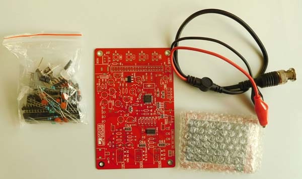
Once you open the kit up you’ll see the two sheets of instructions, one shows the steps to construct the oscilloscope and the other is about using it.
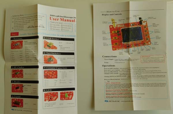
Instructions are good, in full colour and understandable English.
You will also notice the test leads included, the bag of components, the display PCB (which is best left in its protective bubble wrap until needed) and the main red PCB.
One thing to note is that this is a partially constructed kit. All the surface mount components are already soldered. This makes it a lot easier.
If you follow the instructions, which I would recommend with this kit as they actually are correct. You should fit the resistors first. They are quite small and I used a component tester to measure them and then simply fitted what the resistor value said in step 1, all my resistors and values were correct so I soldered and trimmed them to end up with the picture below.

The PCB with the pre-soldered surface mount components and the resistors soldered into place.
Step 2 of the instructions is to fit the HF chokes, there are three of these and they look similar to the resistors. You can identify them from the picture below.

These are HF chokes not resistors.
Solder them in place and trim the leads and you should end up with something like the picture below with L1, L3 and L4 fitted.

HF chokes soldered in place.
Step 3 is to fit the diodes, take care here as the diodes are not the same. D1 is a 1N5819 and D2 is a 1n4004 or 1N4007. They are also polarised so you need to get hem the correct way round. Fit them and you should have something similar to the picture below.

Diodes D1 and D2 in their correct positions.
Step 4 is to fit the crystal, this is easily identified and once soldered into place it should look like the picture below.

The 8Mhz crystal soldered in place.
Step 5 is to fit the mini USB socket, as mentioned in the instructions this component is optional and as I couldn’t find any use of it I didn’t bother fitting it.
Step 6 is fitting the push button switches. You do need to give them a bit of a push to get them to sit properly on the board, they will fit flat against the PCB when pushed all the way down and you will end up with the board looking like the picture below.
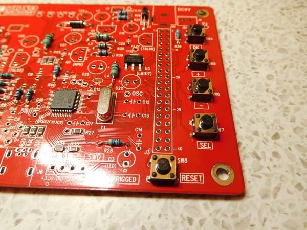
The five push button switches soldered on the DSO board.
Step 7 is the fitting of the ceramic capacitors, these are different values so you need to be careful. There are eleven capacitors that are 0.1uF so solder these in first, then C12 and C13 are the same value of 22pF so identify and solder them. C7 and C8 are 120pF so solder those in next. That just leaves three values left. Easy, just solder those in and you will have a board looking like the picture below.
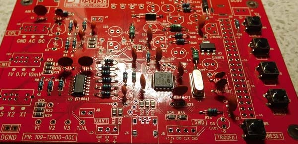
Ceramic capacitors all fitted.
Step 8 is simple and just involve soldering in the LED but just be careful to solder it in the correct way round.

The LED soldered in place.
Step 9 is the soldering of the pin header, as the instructions show have the opening towards the edge of the board as shown in the picture below.
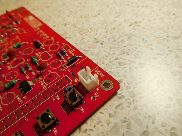
Power connector for 9V DC.
Step 10 is the fitting of the two transistors, again you need to be careful as they are different. One is a NPN and the other a PNP and you must not get them the wrong way round.
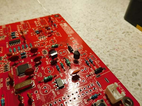
PNP and NPN transistors soldered in place.
Step 11 is the fitting of the regulators. Again they are different, a 78L05 for positive 5V and a 79L05 for negative 5V. Don’t mix them up.
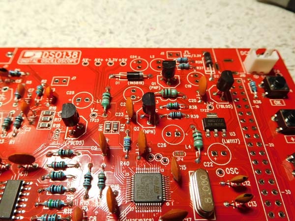
78L05 and 79L05 regulators shown on the left and right of the transistors.
Step 12 is to solder in C4 and C6, the capacitor trimmers, these are easily identified and both the same value and can be fitted either way round, you can’t go wrong with these.
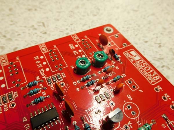
Capacitor trimmers C4 and C6.
Step 13 is to fit the power inductor L2, easy to identify and you simply solder it in either way round

Step 14 is to mount the electrolytic capacitors, there are six of them and they are all the same value 100uF 16v but they are polarised so have to be soldered in the correct way round. The square pad is also marked with a + sign to aid you.
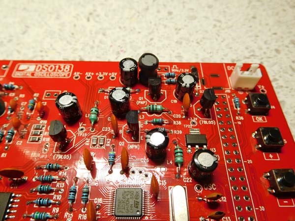
The polarised electrolyic capacitors.
Step 15 is simple, you just solder in the power connector

Step 16 is to solder in the three pin headers J5 and J6. Again this step is optional so I didn’t bother to do it.
Step 17 is to solder in the pin headers of J7 and J8 which are two pin, and J3 which is a forty pin one, they don’t have to be soldered in any particular way round but be careful when you solder in the two pin ones as you can get them to twist slightly, try to get them at right angles to the big forty pin one as they do have to line up with the display board.
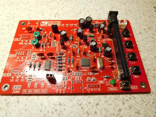
The headers soldered in place, the bottom left one was slightly off on the first attempt as it has to line up to the display board that plugs into the top.
Step 18 is to fit and solder the slide switches. They take a bit of jiggling around to get to fit properly and to get them seated properly in the printed circuit board. Make sure they are properly in place before you solder them.
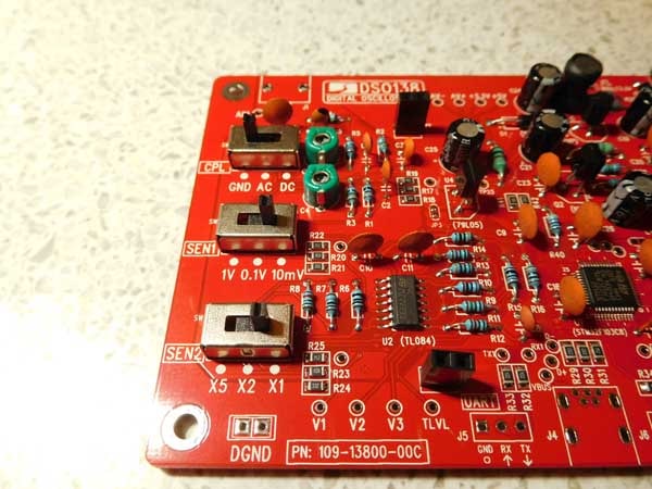
Slide switches mounted, make sure they are pushed flat down before you solder them.
Step 19 is to solder in the BNC connector. I had to put in a larger tip in my solder station and turn up the heat to get this to solder. One of the reasons why a soldering station is a good investment, you can read here about the one I bought. The BNC connector pins for the ground form the whole metal body of it so this will heat up while you solder it and also it will stay very hot for a while afterwards. You really need to get this hot to solder it properly as it will also form a mechanical connection that will take a fair bit force upon connecting the test lead up to it.
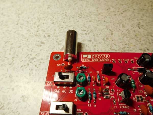
Step 20 is to simply solder a loop of tinned copper wire or an offcut of a component lead. This is the test signal square wave output. You don’t get this in the kit so don’t waste time looking for it LOL.
Step 21 is to solder JP3, this is marked on the board and it’s just two pads adjacent to each other. You just have to put a blob of solder on them to make sure they are joined.
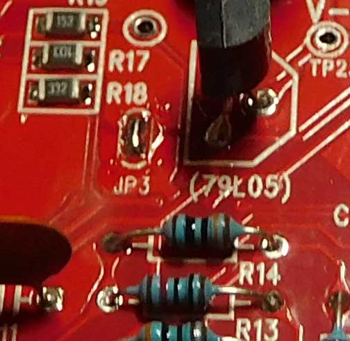
JP3 has a blob of solder to join together the two adjacent pads.
Step 22 is to assemble the display board. J1 is the forty pin header and J2 and j3 are the two pin ones. It’s important and also fairly obvious that these solder onto the back of the board, not the side with the display on.
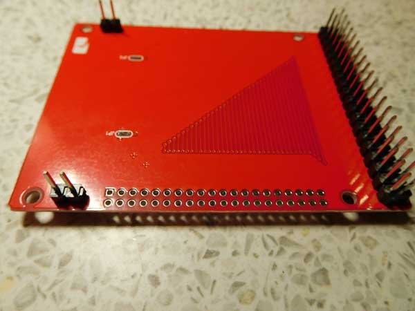
Make sure the connectors are soldered onto the back of the display PCB.
Test and use
You have now completed the soldering stage. Apply a 9V supply to either J9 of J10. You need to be aware of the polarity. I used J10 and using this the conventional centre pin is the positive. With a voltage or multimeter the voltage at TP22 should be around 3.3V. Mine was so it’s looking good so far. As the instructions mention if you get 3.3V at TP22 you can disconnect the 9V voltage supply and put a blob of solder on JP4 and make sure that the adjacent pads are shorted together.
The display board should now be plugged in, if you remember earlier I mentioned making sure the two pin sockets were soldered in square. If this is the case it should be a simply line up and plug in.
You can then reapply the 9V supply and hopefully the LCD will illuminate and you will see the boot up screen. The green LED should also blink and you should be in possession of a working oscilloscope.

The completed DSO 138 oscilloscope kit, powered up and booted.
The button functions are printed in white on the circuit board. If you press the “SEL” select button you will see the various options flash as you press it, pressing the + and – buttons increases or decreases the values.
Mine worked first time without any problems but there is a comprehensive troubleshooting section with voltage references shown on a clear picture. There are also instructions for entering test mode. Because mine worked I didn’t have to try any of this but it does look good and not many other kits have any instructions or help if it doesn’t work.
How to use
That completes the first construction sheet. The second sheet covers “how to use”, the display and controls.
First thing to do is to calibrate the probe and the instructions cover this. I used a standard oscilloscope probe like this one here instead of the supplied crocodile clip one. These instructions are very good and will get you up and running. The back of the “up and running” sheet also contains a full circuit diagram. The only thing I found that didn’t work correctly was the factory reset. Holding down the + and – buttons didn’t do a factory reset on my unit. Maybe the software has been changed?
I personally think some of these entry level devices can get a lot of criticism, this is generally from people who have, and are comparing them with machines costing hunreds if not thousands of pounds. A lot of people as much as they would like can’t afford that sort of money for a hobby and although this type of oscilloscopes is limited it does offer you an amazing piece of test equipment and having one of these is better than not having anything at all.
Let’s not forget that you can do pretty much most fault finding on audio equipment. Having just built a voltage controlled oscillator I was able to see all the waveforms working, check the pulse width control was working and tweak the pre-sets to make the sine wave more siney. My second job of sorting out why a breadboard monostable wasn’t correctly functioning was also a breeze with this oscilloscope, also made easier by replacing the test lead with a proper probe. Simply following the trigger though to where it stopped and I’d found a faulty capacitor.
If you’ve got a few hundred pounds for an oscilloscope then read this and buy one of the excellent scopes you can get for that money. If you can’t afford that sort of money then this is a brilliant piece of test equipment that will enable you to see all sorts of electronic stuff you wouldn’t otherwise be able to.
DSO 138 Oscilloscope case
Once you’ve built the DSO 138 oscilloscope you may want to enclose it in a case for protection. If this is the case (pun intended) there are kits specifically made for the job.
DSO 138 Oscilloscope case instructions
Although the case is excellent unfortunately it doesn’t come with any assembly instructions and I certainly didn’t find it easy and I had to take it apart after making mistakes a few times so I’ve put together my own instructions of how to put it together in one attempt.

The dso138 oscilloscope case kit.
The kit contains everything you need to construct the case enclosure for your DSO 138 oscilloscope. The first thing you need to do is peel off the brown protective paper from the perspex panels. you may find a few remaining bits of squares that haven’t been removed, take them all out before you start assembling anything.
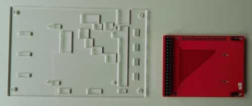
The first perspex piece that you need.
Carefully unplug the display board from the main board. This fits over the panel with the connectors going through the cut outs. The four smallest nuts and bolts in the pack are then use to fix the display board in place.

This is the display board bolted to the panel and shown from the back.
Enter your text here…
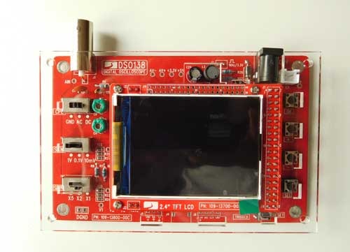
The display board , now mounted on the perspex panel can be plugged back into the main board.

There are two identical panels as you can see from the above picture.
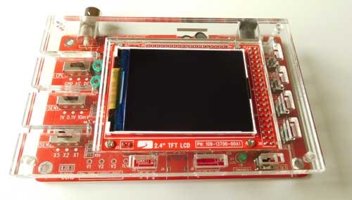
Place these on top of the display board.
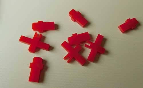
Now it’s time to fit the plastic sliders that go over the switches and push buttons. The push button ones are joined together and need to be snapped apart. You actually get more parts than you need, three for the slide switches and five for the buttons.
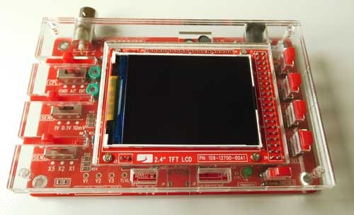
They just drop through the holes in the panel, just make sure you line up the plastic slide switch actuators over the switches.

This is the front panel. when it is placed on top it will hold the red plastic switch actuators in place.

The front panel laid on top of the whole assembly.
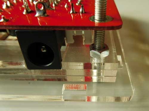
Next put the long bolts through the holes in all the perspex panels. They should all line up, then put a nut after the last panel as you can see in the picture above. don’t tighten the nuts up at this stage. I found it easier to put the nuts on the back of the bolts through the PCB to hold the whole thing together then take each one off and put the nut in the correct place, it’s fiddly and that way at least it holds together while your doing it.

Not many parts left now, take the four side panels, get the one with the round hole in it that fits over the BNC connector. This slots into the holes but you will have to loosen the nuts to make enough of an angle to get the side panel to fit in the holes. Once you have that bit in place you can tighten up all four nuts as you won’t be able to after you put the bottom panel on. fit the remaining three side panels into place in the locating slots and put the other four nuts over the bolts to keep the PCB in place. Don’t over tighten them as you will just bend the board and you will end up with the case like the picture above.

Finally fit the base panel and use the rounded nuts to hold it in place.

The finished assembly of the DSO 138 oscilloscope case kit. I’ve put an Amazon button below if you want to buy one.
How to use the DSO 138 oscilloscope, a practical example.
If you’re wondering whether to buy an oscilloscope or not I was one of those people for years and boy do I now wish I’d bought one before.
It’s one of those things I put in the category that I could save my money and make do without one but after getting one it’s in the category its more useful than I ever imagined and if I’d got one earlier my electronics life would have been a lot easier. By the way two other things that are in that category are the helping hands and the multi tool. I just wouldn’t want to be without them once I’ve owned them. Oh and a light and magnifier have joined them now my eyes are going a bit.
One of the biggest things that put me off owning an oscilloscope was the price but with some pretty decent budget offerings that’s not even a problem now. Having said that with how useful an oscilloscope has been to me I wouldn’t even think twice now at spending a few hundred pounds.
The best way to show how to use any tool is in my opinion to show it being used in a real situation, so that’s exactly how I’m going to start with this oscilloscope. The one I’m showing here is a budget kit model, it won’t do everything but its defiantly better to have one like this that not have one at all if you can’t afford a few hundred pounds.
So here’s the problem. I’ve got a sequencer that’s supposed to be outputting din sync or sync 24, the old Roland standard before midi sync came along. And a drum machine that’s supposed to be able to use din sync as an input.
I still use it for its accuracy and easy of integrating into music equipment.
It’s not working and I have no way of knowing why so cue the oscilloscope.
Maybe the sequencer is not outputting din sync, it could be that there is some setting that needs to be enabled or something so that’s the first check.
Din sync contains an earth connection, a clock signal and run signal for starting and stopping.
The first thing to do is to set the sequencer to run so we have something to see on the oscilloscope screen. Clip the crocodile clip on the probe to a zero volt / earth connection and then touch the probe on to the connection that should be the clock signal. The clock should look like a square wave or pulse wave, the difference between the two is basically the gaps between its high and low times, at the moment we are looking for something going between high and low. Something is flickering which looks promising so we clip the probe onto the soldered terminal so we don’t have to hold it on.

The top slide switch is set to DC. The second slide switch is set to 1V and the third to X1.
I’m expecting the signal to be going between about zero and five volts so set the input to be DC and 1 volt. That means it will show one volt per cm on screen, the grid overlay is in 1cm divisions.
The trigger is set to auto and by selecting the time base and speeding it up the green trigger LED on the oscilloscope flashes and the displayed waveform on the oscilloscope screen becomes stable.
As we are in DC mode there shouldn’t be anything below halfway on the screen, if there is I’ve got something drastically wrong! There are only so many cm graduations on screen so you can see better if you lower the horizontal axis to show the full picture.
Now we have a good view of what’s happening. There’s a square wave on screen, it’s more of a pulse width to be honest so its definitely some form of clock, it’s also spread over five of the graduations, so as we set it to 1V per division it’s about five volts this is exactly what I would be expecting to be on the clock signal so I think it’s fair to say that ok. Pressing the display button on the oscilloscope shows a few additional measurements, it tells me that the frequency is 23 Hz and the maximum voltage is 4.89 V with the minimum being 0.1V. This confirms that there is a clock signal and it’s at the correct voltages.

This shows that we have a clock signal going between high and low. Using the probe you can follow where it goes .
Disconnecting the probe and clipping it on to the run signal shows a horizontal line at the position of the top of the previous signal. Pressing the stop button on the sequencer sees this horizontal line drop to the bottom. So pressing the stop and start buttons one the sequencer see the run stop going between high and low levels similar to that of the clock which is again what I would expect to see if everything is correct. Now we have the oscilloscope set to show what we can see there’s no need to change any of the settings.
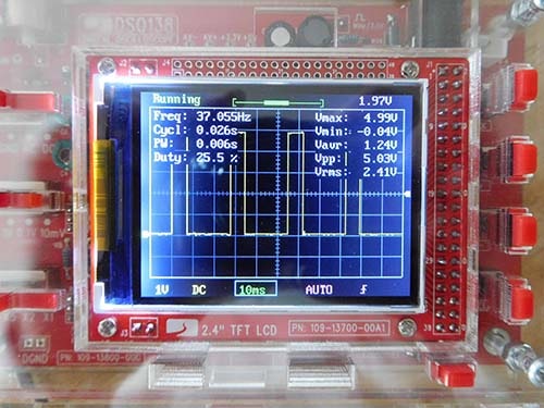
You can get more useful information by pressing the “display” button. You can see the frequency and the fact that the wave is a pulse wave about a quarter of a square. you also get a reading of the maximum and minimum voltages.
If we now plug a din sync lead into the output of the sequencer and the input of the drum machine we can do further checks just moving the probe.
By disconnecting the crocodile clip from the sequencer and clipping it a suitable 0v / earth connection and touching the probe on the back of the input socket terminals we can now see that the clock and run stop signals are there. This shows that the earth connection between the two bits of equipment is there and that the sequencer is outputting the correct din sync signals and that they are making their way correctly down the lead and into the drum machines din sync input socket so the lead and connectors must be ok.
By looking on the circuit diagram of the drum machine I can see that the clock and the run signals pass through a transistor each and into two pins of the PIC, that is basically the whole drum machine controller. I think it fair to presume the transistor / resistor arrangement is there to protect the inputs to the PIC from too much of the wrong voltage. By touching the probe onto the two inputs on the PIC I can check that the clock and run signals are making it all the way to where they are supposed to be.
It’s a bit like a stethoscope where a doctor can hear what’s happening at various stages. As we’ve set the oscilloscope up to show the “clock” and “run” waveforms we can touch the probe on to connections to see what’s happening in a similar way.
One thing that I have noticed is that although the clock waveform and run stop signal get through to the correct pins of the PIC they are a little smaller the when they come out of the sequencer. By smaller I mean less in amplitude, not the full voltage. Using the display button again indicates that the “clock” and “run/ stop” signals are nearer to 3V than the original 5V that came out of the sequencers outputs. As they are both the same levels it’s a decent assumption that the levels are being lost through the transistor / resistor input protection. Could this be the problem that the signals aren’t large enough for the drum machine to count as full on and offs?
As we’ve measured the clock and run signals using the oscilloscope we know that they are between zero and five and by connecting them directly to the PIC we shouldn’t do any damage so we can safely disconnect the input protecting transistors / resistor circuit and directly connect to the sync and run signals to the PIC inputs. This will then verify if the signals are too low after going through the protection circuitry.
After connecting directly to the PIC inputs it would still not run in sync. I quickly switch the sync and run signals over as I’ve seen them incorrectly wired in circuits before but that still didn’t help neither did altering the sync input settings on the drum machine.
So not exactly the results I was looking for. I can only conclude that din sync isn’t correctly implemented in the software of the drum machine as the correct levels and frequency of the clock and run signals are getting right to the two pins on the drum machine PIC.
Although it wasn’t what I wanted. I’ve found out that the sequencer was sending the correct din sync signals the sockets and leads were working and wired correctly and that they were getting to the correct terminals right to the drum machine controller and that even skipping the input protection transistors to get directly to the controller didn’t work, we could see that the signals were correctly there. Something that I could only do with an oscilloscope. Even a cheap one gives me the full confidence that it’s not something I’ve done wrong.