
![[easyazon_link identifier="B085XZMHVM" locale="UK" nw="n" nf="n" tag="wwwmovinghous-21" cart="n" cloak="n" localize="y" popups="n"]Breadboards[/easyazon_link]](https://www.bestsoldering.com/wp-content/uploads/2022/02/Breadboard-voltage-controlled-amplifier.jpg)
Build a Breadboard voltage-controlled amplifier project
This breadboard voltage-controlled amplifier project uses few components but produces an excellent VCA.
If you are a beginner in electronics and breadboard construction you may want to check out my article Breadboard tips before you jump into the construction.
I have built this circuit and taken it apart to rebuild it again just following my instructions in order to try to get rid of any mistakes and find any omissions. It’s not much fun to spend a lot of time building something only to find it won’t work.

What is a VCA?
A VCA or voltage-controlled amplifier to give it its full title is a type of automatic volume control rather than an amplifier.
You connect an audio signal to it and a control voltage. When the control voltage is at 0V no signal gets through. When the control voltage is at its maximum so is the signal level. It’s that simple.
It’s commonly used with an envelope generator to produce the attack, decay, sustain and release of a sound in synthesizers.
You can also use a low-frequency oscillator or LFO connected to the control input to produce tremolo effects or speeding up the oscillations to audio frequencies will produce ring modulation effects for all you Dalek voice lovers. You can also use two modulation sources using an LFO and envelope generator to introduce a delayed vibrator. There are loads of things you can do with a VCA. OK, you say you’ve convinced us to build one let’s get on and do it.

Constructing the breadboard voltage controlled amplifier
I’ve constructed this VCA to be built on the same breadboard as the breadboard filter project. That is why it’s on the bottom half if you were wondering. It can be set up to work from 0 to 5V or 0 to 9V depending on the rest of your synthesizer. If you are going to build it to be used with the breadboard envelope generator project then I’ve given instructions for it to set up for the 0 to 5V range.
In this project, I’m using both blue strips for 0V and both red strips for 5V so you should link them up together as I have in the diagrams. Also before you start check that your breadboard has the red and blue strips in the same places as the diagram. Some are different if yours is you might want to alter them like I have in my “Breadboard tips” article.
Breadboard VCA parts list
Resistors
5 x 100k
3 x 10K
2 x 22K
3K3
330R
2 x 50K presets
1k preset ( I use the 3296W type as they are multi-turn for precise settings and they plug directly in with a simple pinout only taking up 3 .1 spacing holes.)
Capacitors
15pF ceramic
100nF ceramic
ICs and semiconductors
TL084 or TL074 quad op-amp
LM13700 dual transconductance op amp
4V7 zener diode
The breadboard and wires, of course, you need something to build on and some wires.
Check out my article on breadboard wires.
Construction instructions
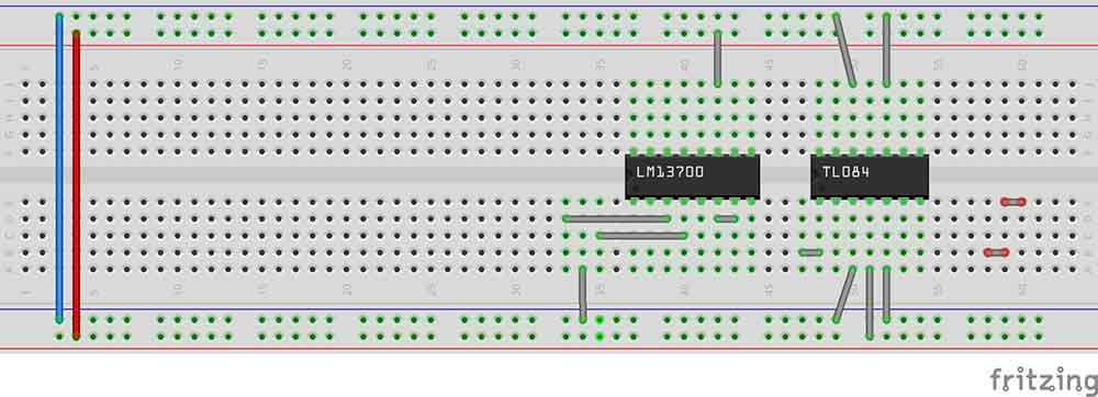
Start by inserting the wire links. It’s easier to get the smaller things in first.
1. link 42j to red
2. link 50j to blue
3. link 52j to blue
4. link 34a to blue
5. link 50a to blue
6. link 51a to red
7. link 52a to blue
8. link 33d to 39d
9. link 35c to 40c
10. link 42d to 43d
11. link 47b to 48b
12. link 58b to 59b
13. link 59e to 60e
If you are building this project on its own link the two red and blue strips together. If you are building it on the same board as the voltage-controlled filter you will already have these links in place.

14. LM13700 pin 1 to 37e
15. TL084 pin 1 to 48e
16. 330R resistor 45i to 48i
17. 3K3 resistor 60d to red
18. 22K resistor 54h to 58h
19. 22K resistor 54c to 55c
20. 10K resistor 38a to red
21. 10K resistor 48d to 53d
22. 10K resistor 53b to 57b
23. 100K resistor 45c to 49c
24. 100K resistor 53c to 54d
25. 100K resistor 45h to 49h
26. 100K resistor 53g to 54g
27. 100K resistor 53i to 57i
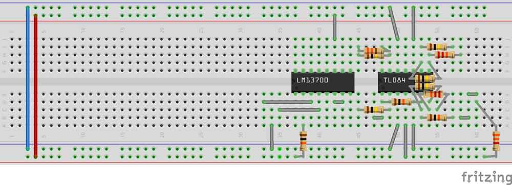
28. 15pF capacitor 48g to 49g
29. 100nF capacitor 60c to blue
30. Zener diode 60b to blue (band on the diode to 60b)
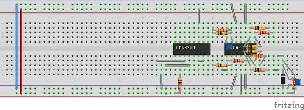
Connect the insulated wire links
31. black wire 43c to 51g
32. white wire 39b to 58f
33. yellow wire 41d to 49j
34. yellow wire 37b to 55a
Plug in the presets
50K preset to 47a, 48a and 49a
50K preset to 57a, 58a and 59a
1K preset to 33e, 34e and 35e
The power supply connects up to -12V to 51h, 0V to blue and +12V to red.
Control voltage connects to 45a.
Audio input connects to 57j.
Audio output connects to 45j.

Shown above is the completed diagram of the breadboard voltage-controlled amplifier.

Other notes
You should really put decoupling capacitors on the supply lines, as close to the ICs as you can get them once you’ve got everything working. Do you know about decoupling capacitors? If not check out my article on decoupling here. The diagram above shows the locations and numbers of the presets to adjust in the calibration process below.
Calibrating the breadboard voltage controller amplifier
To set up and calibrate the breadboard VCA you will need a multi-meter and a separate 5 Volt DC supply.
Firstly set all three presets to roughly their middle positions. You don’t have to be accurate here just guess.
Next, connect up a 5 Volt DC signal to the control voltage input and the signal input and adjust the 50K preset VR2 so the voltage at the output is about 2.5 volts. Again you don’t have to be spot on.
1. Leave the 5V connected to the CV input but connect the signal input to 0V. Then adjust the 1K preset VR3 so the voltage at the output is 0V.
2. Now connect the CV input to 0V and the signal input to 5V and adjust the other 50K preset VR1 so the voltage at the output is 0V.
3. Next connect up 5V to the control voltage input and the signal input and adjust the 50K preset VR2 again so the voltage at the output is about 5 volts.
Finally, repeat steps 1 to 3, you will only be making small adjustments now and you will just need to tweak them a bit until it’s about as good as you can get.
Final thoughts on the breadboard voltage-controlled amplifier project
The breadboard voltage-controlled amplifier project can be built and used for many applications. It is a fully functioning unit as it stands however it is also used in my How to Build a Breadboard Synthesizer article.
Finally, if you have any problems getting this to work check out my article on common breadboard mistakes to see where you could have gone wrong.
Also check out my post, Breadboards – the complete guide, for everything you need to know about breadboards.


“Hi, I’m Graham Moore and I’ve been building electronic projects since I was 12. I had a fascination for old radios and taking them to pieces but when my Nan bought me an electric soldering iron, I realised with a few components I could build stuff.
Learning to solder opened up many doors for me as electronics also became a career. I hope you get as much from it as i did”.
Breadboard design software

Breadboard design software tested and compared If you use breadboards, you might find breadboard design software helps with your building. Breadboards are tremendously useful for beginners who can’t solder…
Breadboard vs stripboard

Breadboard vs stripboard Which is the best method for building prototype circuits? Breadboard vs stripboard, which is better? In this article, I’ll explain the advantages and disadvantages of each method….
Best breadboard kit buyers guide

Best breadboard kit buyers guide In this “Best breadboard kit buyers guide”, I’ll attempt to point you in the direction of the kit that best suits you. Breadboard kits come…
Common breadboard mistakes

Common breadboard mistakes If your breadboard circuit doesn’t work don’t worry you are not the first and won’t be the last. Fortunately, there are a lot of common breadboard mistakes…