

Common stripboard mistakes
There’s nothing more frustrating than completing a circuit on a stripboard only to find out it doesn’t work. OK, there are other things but it’s still pretty bad, right? Fortunately, there are several common stripboard mistakes that people make.
Over the years I’ve seen all sorts. While there are still circuits around in books and on the internet that are wrong and don’t work, the most common reason for a circuit not to work is a mistake by the person building it.
I’ve compiled a list of the most common problems and faults for you to work through to find out why your circuit is not working.
If you have even the slightest interest in things stripboard related then check out my post Stripboards – the complete guide. I’m sure you’ll pick up at least one tip to either save you time or money!
Check your layout is the same as your circuit diagram
I use the LochMaster software to do a printout of the stripboard layout. I then do a printout of the circuit diagram.
Then I use a highlighter pen and draw each component and connection on the circuit diagram. I then do the same on the stripboard layout. This is to confirm both are electrically the same.

It’s easy to forget to cut a track where you meant to do it. LochMaster has a feature that highlights all connections.
You click on a track and it will show all connections to and from it. This is very useful as you can see everything that the node is connected to. You can see exactly where it should go and where it shouldn’t.
Everyone makes mistakes and this is the best way I’ve found to discover them.
Bad solder joints – the most common Stripboard mistake
This is one of the most common faults in electronic construction full stop.
If you are just starting out in soldering, check out my Learn how to solder – a beginners guide.
Even if you are experienced in soldering sometimes there is something on the board or component that stops a decent soldering joint from being made.
Inspect all the joints on the board if there are some that appear to have too much solder then desolder them and remake the joint. If you aren’t sure about desoldering, check out my Learn how to desolder – a beginner’s guide.
When I checked the layout and circuit were the same and I couldn’t see any bad solder joints I remade all the solder joints on the stripboard, removing solder where there was too much.
Sometimes the circuit works after doing this. Very occasionally you will solder a joint that looks OK but isn’t.
Information
Where would electronics be without soldering? Unbelievably, the modern soldering iron was patented way back in 1896 by Richard Schneider and August Tinnerhol and was known as an “Electric heating apparatus”.
Solder bridges
Once you are sure that your circuit diagram and stripboard circuit layout are the same, the next thing to check for is solder bridges between adjacent tracks.
This is particularly easy to do on stripboard as there is no solder resist mask to protect the gaps between the tracks from solder.
You should check with a magnifier as sometimes there are tiny splashes of solder that are as fine as single strands of wire. You can also use a multimeter to double-check tracks next to each other.
Common stripboard mistakes – Tracks not cut
Make sure you haven’t forgotten to cut a track. Everyone does it. As I use LochMaster to produce a stripboard component overlay, track cuts are marked on this. If they correspond to component holes ( remember you can save space by cutting a track between two holes) I poke a PCB drill bit through the hole, then flip the board over to check that it’s cut and that it’s in the correct place.
Make sure you cut the track properly.
Again use a magnifier as sometimes small bits of copper remain where the cut should be and sometimes the copper fragments make their way between other tracks where they shouldn’t be.

Common stripboard mistakes – Components values wrong
While the circuit diagram and layout may be the same, you may have an incorrect component value. This is easy to do with resistors and capacitors being so small these days. Double-check and use a magnifier if necessary to help you read the values.

Faulty components
This isn’t the most common thing to cause problems however it is worth bearing in mind if you’re working your way through this list. I reuse quite a few electronic components when I can so I use a component tester to verify that they are working before I go to the trouble of soldering them in.
The component tester will check resistors, capacitors, diodes and transistors of all kinds. It also will read the value of resistors and capacitors so which helps with the above problem of wrong value components.
When it comes to ICs I try to have a spare to substitute. It’s the best way to check an IC and you did use a socket on the stripboard, didn’t you?

Common stripboard mistakes – final thoughts
If you got this far and worked your way through the above steps, hopefully, you’ve found the fault and got your stripboard circuit working.
Stripboard is easy to make mistakes on. It’s especially easy to put a component lead in the hole next to where it should go. All the holes look the same from the top on a blank stripboard.
I’ve been building circuits on stripboards for years and I still make mistakes.
On a circuit I recently built, it didn’t work and going through the list I’d made two of the above mistakes.
One of the tracks I’d cut still had a small piece of copper linking it. There was also a small solder splash linking two adjacent tracks together. I’d skipped checking with a magnifier and continuity tester!
You may also want to check out my post on stripboard tips. This will hopefully give you some help and advice on building stripboard circuits in the future.
Information
The standard .1-inch spacing Stripboard was invented around 1959. It’s still used today because of its versatility.

“Hi, I’m Graham Moore and I’ve been building electronic projects since I was 12. I had a fascination for old radios and taking them to pieces but when my Nan bought me an electric soldering iron, I realised with a few components I could build stuff.
Learning to solder opened up many doors for me as electronics also became a career. I hope you get as much from it as i did”.
Breadboard vs stripboard

Breadboard vs stripboard Which is the best method for building prototype circuits? Breadboard vs stripboard, which is better? In this article, I’ll explain the advantages and disadvantages of each method….
What’s the best stripboard?

Stripboard has been around for a long time and its still manufactured and bought in large quantities. It has, and will still remain hugely useful for electronic hobbyists to build,…
Lochmaster 4.0

Lochmaster 4.0, is it the best stripboard layout software? I have tried a few of the other available stripboard layout designer software packages. There is some very good free software…
How to use veroboard
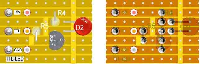
How to use Veroboard or Stripboard In this article, I will attempt to explain how to use veroboard. The theory of veroboard is simple and the idea is fantastic. It’s…