
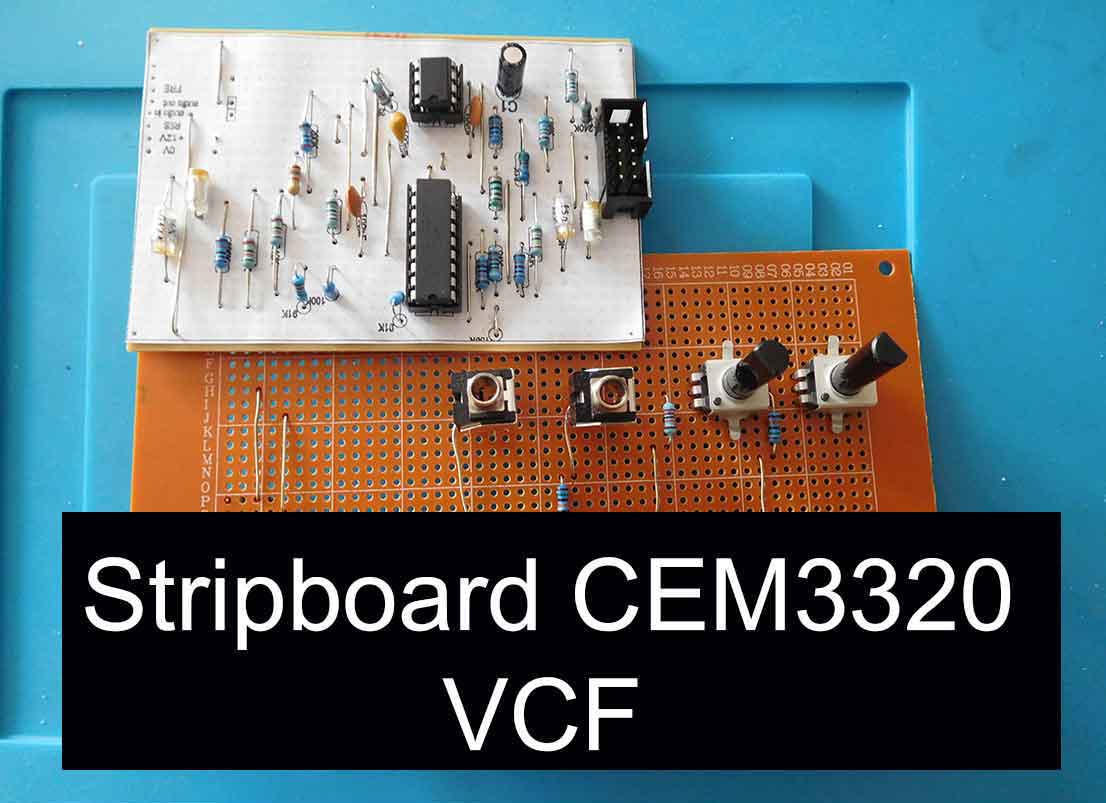

Stripboard CEM3320 VCF
To go along with my stripboard CEM3340 VCO I needed a stripboard CEM3320 VCF. This simple design is similar to the filter circuit on the Sequential Circuits Prophet 1 synthesizer. It is well known as a very good-sounding voltage-controlled filter.
I first built the circuit on a breadboard. You can see the post for the breadboard CEM3320 VCF layout here.
If you have even the slightest interest in things stripboard related then check out my post, Stripboards – the complete guide. I’m sure you’ll pick up at least one tip to save you time or money!
The stripboard CEM3320 VCF circuit
There are some filter circuit designs that use the CEM3320 as a switchable high, low and band pass filter. This uses at least a three-way three pole device and the wiring can be quite complex. I decided that I would just keep the design simple and just configure it as a low-pass filter. After all, it was good enough for the Pro 1 so it’s good enough for me.
The stripboard layout

Similarly to my stripboard CEM3340 VCO stripboard layout I’m going to build this design on two stripboards and link them together with single in-line female connectors and single in-line gold pins in strips. This means it can be plugged and unplugged without any de-soldering. It also has the advantage that you have two boards to fit all of the components on rather than one.
This is quite important if you want to make the whole project small enough to go in a euro rack which is a popular way for modules to be built and used these days.
For extra details about this Eurorack method of stripboard construction check out my guide.
The size of the stripboard that I have used is 24 strips by 37 holes and this is small enough to fit behind a euro rack panel.
Stripboard CEM3320 VCF – Stripboard panel

In its current form my design for the potentiometers and sockets board prohibits it from going into a euro rack format however as the main board will fit it won’t take too much to redesign the panel board.
As it was I had a few of the larger boards suitable to quickly knock up panel boards and my main objective was to get something working quickly.
If I don’t do this I tend to end up involved with projects that drag on and on and never get finished. At least this way I’ve got something usable.

Back to the two stripboard method and its advantages. Another one is that it really cuts down the interwiring of the potentiometers and sockets and other front panel components.
It was after I’d built a euro rack PCB kit that was configured this way that I thought it would be a good idea to try to replicate it when I next used stripboards for a layout.
Using the euro rack standard to supply the power to the board also means that everything can just be plugged and unplugged. This helps when there is no de-soldering if you have to do any fault finding or modifications.
I’m pretty sure that there will be some future modifications.
Oh, and if you’re not that good at desoldering, check out my full desoldering guide for some great tips to help.

Stripboard CEM3320 VCF Components
Using front panel components on a stripboard means you will need to use PCB mounting components. For potentiometers, I use the Alps Alpine RK09K1130 range or the Bourns PTV09 series. These are both the 9mm ones and the three legs are spaced at .1 inch. This also makes them perfect for plugging into breadboards. For that reason, I keep a few standard values in my breadboard kit. It makes for very quick trying out and testing circuits.

Using them also simplifies the layout on the stripboard especially if they are supplying a control voltage. You can have 0V and +12V run up the strips with the potentiometers on the outside legs.
If you use the PCB mounting 3.5mm sockets on the front stripboard they will be the correct height for the PCB mounting potentiometers. You can then use the nuts on the sockets to hold this board to the front panel and have the component stripboard plug into that. Then both boards and the front panel will be held together without having to drill holes in the front panel for fixings or brackets. Easier and neater, everyone’s a winner.

Stripboard CEM3320 VCF – Circuit Operation
The stripboard CEM3320 VCF operates in a simple low-pass mode. There is a manual frequency control and a manual resonance control. This is in keeping with the Sequential Circuits Prophet one design. Looking at other filter designs using the CEM3320 it is a simple modification to wire in another 3.5mm socket for voltage control of resonance. This would make this simple filter circuit even more versatile.
Building stripboard tips
When building on a stripboard there are a few things to consider.
First, you have to cut tracks. I have a post just about cutting stripboard or Veroboard tracks here if you want more information.
The biggest mistake you will make using stripboard is to put a component or link in the wrong hole. It’s just so easy to do as you have lots of counting to do. I can check and double check but I still manage to do this.
The best thing I ever did once I got more into building circuits on stripboard was to use design software.

Tip – Always use IC sockets
The cost is minuscule compared to the ICs and there’s no easier way to check if an IC is working.
You just unplug it from a socket and plug it into another one.
Stripboard design software
I’ve found that using Stripboard design software makes creating layouts a lot easier, so check out my article if it’s something you need. My favourite is Lochmaster and if you click here you can find out why.
Apart from the fact that you save lots of paper, pencils and rubbers, you can move components around. You can either compact up a circuit or if you have already decided on the finished stripboard size expand the components to fill the space available.
Then once you have finalised the layout you can print out a black and white component overlay.
The software is easily calibrated so you can get your printouts spot on. Next, make holes in the four corners of the printout. Then you can align it to the stripboard and tape or glue it in place. You can then use a small drill bit or needle to poke holes where the components and links go.
No more miscounting and soldering something in the wrong place.
If you look at the picture above, you’ll see how easy it is to see the components and links are in the correct place.
I built four identical large, complex stripboard layouts using this method and all of them worked the first time. I couldn’t have possibly done this without the printed overlay.
I’d argue that a printed overlay on a stripboard is even more important and useful than the component overlay on a printed circuit board.
There are only certain places for a component to go on a PCB. On the stripboard, it can literally go anywhere. A component one hole away from the wrong place can destroy a component at worst or have you scratching your head as to why your board is not working.

Final thoughts about the stripboard CEM3320 filter
For this actual layout, I used the AS3320 compatible. You can get these for around £5 on the internet if you shop around. This is significantly less than I paid when I bought Curtis CEMs for my Electronics and Music Maker Spectrum Synthesizer all those years ago.

If you aren’t familiar with the E&MM Spectrum Synthesiser, it was a kit synthesiser that was featured in the Electronic and Music Maker magazine. It used the Curtis Electromusic range of integrated circuits. The Sequential Circuits Pro 1 synthesiser also used these same ICs.
Information
The Sequential Circuits Pro 1 was used for lots of the sounds on the Yazoo – Upstairs at Eric’s album.
Vince Clarke says it is his favourite synthesiser of all time.
I have also done articles on building other Stripboard projects to go with the CEM3320 Fiter. These are building a CEM3310 stripboard envelope generator, the stripboard CEM3340 Voltage controlled oscillator and the Stripboard MIDI to CV converter.
If you are interested in the Sequential Circuits Pro 1 synthesiser, I have an article on building a complete synthesiser on breadboards, along the lines of the Pro 1.


“Hi, I’m Graham Moore and I’ve been building electronic projects since I was 12. I had a fascination for old radios and taking them to pieces but when my Nan bought me an electric soldering iron, I realised with a few components I could build stuff.
Learning to solder opened up many doors for me as electronics also became a career. I hope you get as much from it as i did”.
Hide Ads for Premium Members
[quads_disable_ads_form]
555 monostable calculator

555 monostable calculator Download the 555 monostable calculator to easily work out the time from the components. Once you have downloaded the spreadsheet, all you have to do is input…
555 astable calculator

555 astable calculator Click further down the page for a downloadable 555 astable calculator. If you’ve joined this guide from the 555 operating modes page or even if you haven’t,…
555 timer modes

555 timer modes The 555 timer has 3 main modes of operation. These three 555 timer modes are astable, monostable and bistable. You can achieve each of the modes by…
How to test a 555 timer

How to test a 555 timer This guide will show you how to test a 555 timer. I’ve covered testing many types of electronic components before and this tends to…
Capacitor value codes

Capacitor value codes Capacitor value codes are often used to indicate the value of a capacitor. Whereas resistors have usually stuck to a standard colour code (well standard-ish as it…
Lite windows with DAWs

Lite Windows with DAWs I wondered how much performance boost I’d get using Lite Windows with DAWs. The test results were shocking! A few years ago I decided to use…
How to connect Kodi to a network drive

How to connect Kodi to a network drive If you need to know how to connect Kodi to a network drive, it will depend on your particular network drive. I’m…
Can you solder without flux?

Can you solder without flux? The simple answer to can you solder without flux is no. The good news is that if you have got some solder it’s more than…