

Breadboard blinking LED project
A breadboard blinking-LED project can be achieved in a number of ways. Most of them use a multi-vibrator in some way like using a couple of transistors. I’ve shown this idea in my article simple electronic breadboard projects if you want to check that out.
Others use a dedicated integrated circuit. I’ve shown that too in my article Simple LED flasher circuit using 555 timer IC if you want to check that out.
Breadboards are great for building projects large and small. Building flashing LEDs is a small project but you can build huge projects on breadboards. I’ve built a complete synthesiser on breadboards.
I’m going to show you a less popular method here that is quite complex but you will be learning a lot along the way. You’re going to be making a blinking LED by using a microcontroller and by doing that successfully you will have learned some basic programming skills.
This is a very good introduction into the world of microcontrollers in hobby electronics. I steered clear of microcontrollers because of the perceived complexity however once I scratched beneath the surface and took a step-by-step approach to learning it all became a lot clearer and I’m certainly glad that I did.
Don’t forget that if it doesn’t all go smoothly and you encounter any problems, have a look at my Common Breadboard mistakes. Work through the list to see if you’ve made any.
Information
The modern plastic breadboard in use today, with .1-inch spacing holes was patented in 1971 by Ronald Portugal.
What you will need for the breadboard blinking LED project
A breadboard and some wires, an LED and a 390R resistor, and an ATtiny85 microcontroller.
A laptop with some free software installed and a USBasp.
Once you have programmed the Attiny85 microcontroller you only need three components on the breadboard. The ATtiny85, the resistor and the LED. You don’t get much simpler than that.
Building the breadboard blinking led project
This is the breadboard layout.

The resistor connects to pin 3 and then to the LED. The negative goes to pin 4 and the positive to pin 8. Connect it up to a 5-volt power supply and you will have a blinking LED.
You need to program the microcontroller first before you can do this so build this circuit on the breadboard then get hold of the USBasp. The USBasp has a ten-pin connector at one end. This is so it can perform something known as ISP.
This is a way to serially program microcontrollers while they are in circuit and powered up. The advantage of this is that you don’t have to remove them. This also means that tiny surface mount devices (SMD) can be used. You can’t unplug a SMD device so it’s the only way you can program them.
ISP usually has 6 pins but there is an adapter board that you can get for the USBasp. Sometimes you get the 10 to 6-pin adapter board when you buy the USBasp. You can wire the 10 pins up to the breadboard but using the 6-pin adapter makes it easier.
Firstly you only have 6 pins to connect so there is less chance of making a mistake. Secondly, the connections are labelled on the adapter which makes a lot more sense when you connect it to the breadboard.
You can also buy complete breadboard kits click here for more information. These are particularly good for beginners.
Powering the microcontroller for the breadboard blinking LED project
The USBasp has a three-pin jumper arrangement in the corner of the board and a two-pin link. This is so you can control if you want the USBasp to power the microcontroller.
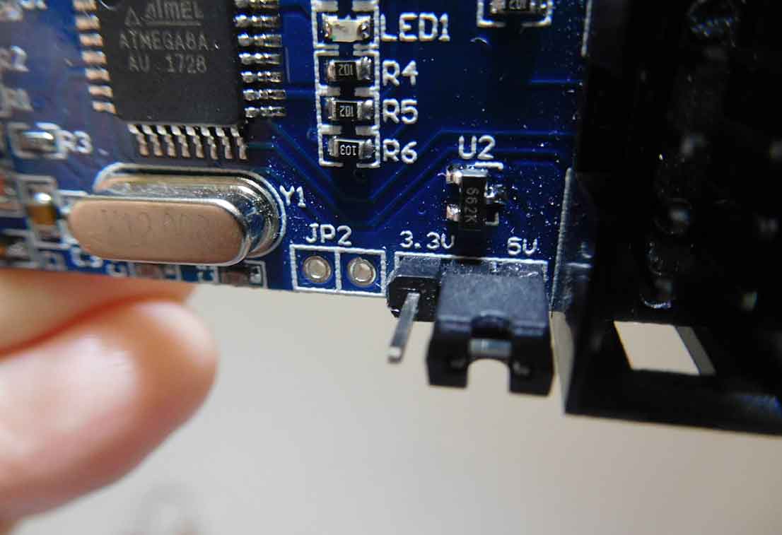
You can see that it has a 5 V and 3.3 V label on either side. In the picture, the USBasp is providing 5 V to the microcontroller. Plugged into the other two pins and it would provide 3.3 V.
I’ve used it to program large complex ATmegas on printed circuit boards where the boards were powered up. In that instance, I didn’t want to power the microcontroller and so I took off the link.
We are going to get the USBasp to power the ATtiny85 so the link needs to be in the 5V position as shown in the picture.

Wiring the USBasp to the breadboard
So let’s assume we’ve got the adapter board. Connecting to the adapter board is a lot easier with the patch leads that I mentioned in my Wires for Breadboard article so those are the types I’m using.
Starting on one side of the adapter, plug one into GND and the other end to pin 4 of the ATtiny85. Next down is MOSI so plug that in and the other end to pin 5. The last one on that side is VCC and that goes to pin 8.
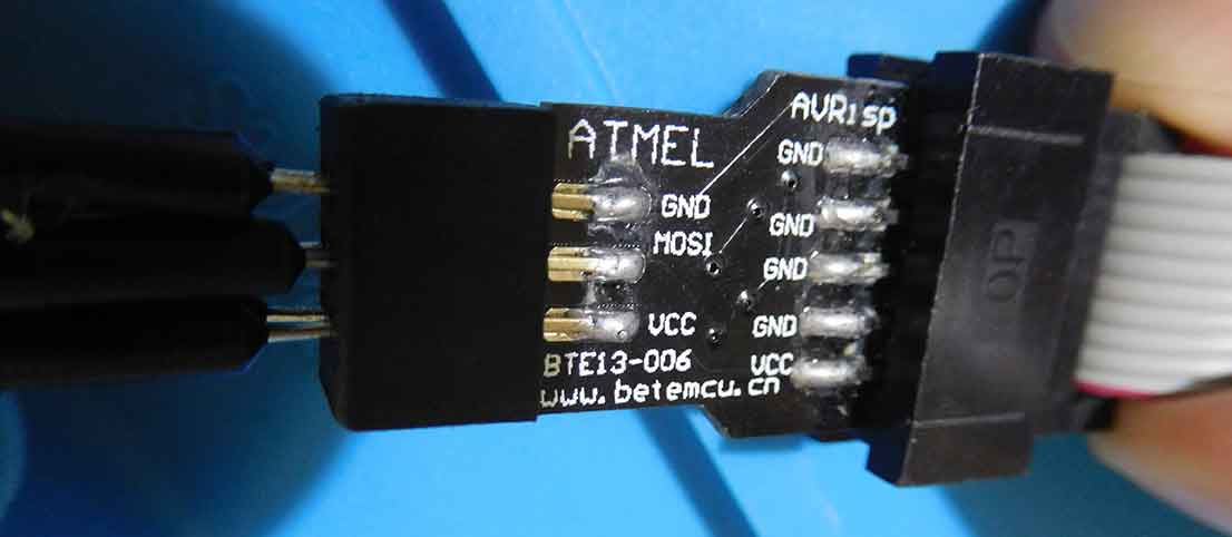
On the other side of the adapter, MISO goes to pin 6, SCK goes to pin 7 and RST goes to pin 1.

That’s all six wires from the adapter board going to the breadboard. You should now have the USBasp and the breadboard looking like the picture below.
What about the software?
You will need to have Arduino IDE installed on your laptop. It is available to download for free however it is really good and works so if you can afford to donate to the software please do. You can download the Arduino IDE here.
Once you have Arduino IDE installed you need to install support for the ATtiny range. You can do this in Preferences by pasting the link:
This goes into the box, Additional Boards Manager URL: Then click on board and board manager then scroll down to the ATtiny package. Once you have done that select from the “Tools” menu, Board: “ATtiny25/48/85”, Processor: “ATtiny85” and Clock: “internal 1 MHZ”. Then select Programmer: “USBasp”
Loading the blink sketch
Once you’ve done the steps above you are ready to load in the “blink” sketch. You do this by clicking on File/ Examples/ 01. Basics/ Blink.
Once this has opened you have to make a few alterations to the basic sketch as it’s for the Arduino UNO board. Look down the page where it is displaying the code and you will see three occasions of the text “LED_BULTIN”. Replace all three with “4” as we are using PB4.
Next, click on the tick symbol which compiles the code. It only takes a second then click on the arrow next to it which uploads the code to the ATtiny85 microcontroller. This also only takes a second and the LED will now be flashing.
You can play about with the numerical values of the HIGH and LOW settings. By default, they are both set to 1000, try lowering them to 500 first. The HIGH is the time the LED is on and LOW is the off time.
If you want more detail on setting up the software check out my guide here for a lot more detail and extra help and information.

Final thoughts – Breadboard blinking LED project
While there are many ways to build a Breadboard blinking LED project I think this method teaches you loads once you know how to build basic circuits on breadboards.
Being able to program microcontrollers opens up a lot of doors in hobby electronics and once you’ve learned how to program one they are all fairly similar just with different and sometimes larger pinouts. That’s why it’s good to start with a basic 8-pin tiny microcontroller.
Using just the ATtiny85 and a handful of other components you can build some quite complex devices. Years ago I built a MIDI (Musical Instrument Digital Interface) to CV (Control Voltage) interface.
It used around 10 ICs and was quite a build. You can build a MIDI to CV interface using the ATtiny85, an opto isolator and a few other components.
Don’t forget you can buy complete breadboard kits to get you started.
Also check out my post, Breadboards – the complete guide, for everything you need to know about breadboards.

“Hi, I’m Graham Moore and I’ve been building electronic projects since I was 12. I had a fascination for old radios and taking them to pieces but when my Nan bought me an electric soldering iron, I realised with a few components I could build stuff.
Learning to solder opened up many doors for me as electronics also became a career. I hope you get as much from it as i did”.
Breadboard design software

Breadboard design software tested and compared If you use breadboards, you might find breadboard design software helps with your building. Breadboards are tremendously useful for beginners who can’t solder…
Breadboard synthesizer

Breadboard synthesizer This breadboard synthesizer project was inspired by wanting to build something really good on a breadboard. There are plenty of breadboard projects for flashing lights and stuff like…
Best breadboard kit buyers guide

Best breadboard kit buyers guide In this “Best breadboard kit buyers guide”, I’ll attempt to point you in the direction of the kit that best suits you. Breadboard kits come…
Wires for breadboards

Wires for breadboards What wire do I use for solderless breadboards? Let’s start with what not to use. Don’t use stranded wires for breadboards. Stranded wires They will be difficult…
How do breadboards work?

How do breadboards work? Before you can answer the question how do breadboards work, you need to know exactly what a breadboard is. Firstly, there are various types of breadboards…