

Simple electronic breadboard projects
This is probably one of the most simple electronic breadboard projects there is. It only has two components. A resistor and a light emitting diode or LED as we’ll now refer to it. This circuit lights the LED.
Unlike a light bulb, you can’t just wire it across a power supply. Depending on the voltage, it would more than likely burn the LED out. You have to limit the current flowing through the LED and that’s what the resistor is for.

If the LED doesn’t light just turn it around. You won’t damage it by connecting it the wrong way around.
If you had stayed awake in your school’s physics classes you may have learned some theory that may have been useful now. That theory is Ohm’s law and I’ll confess to not listening or learning it while I was at school. I have read and learned since as it has become more relevant.

Ohms Law
Ohm’s law is the relationship between voltage, current and resistance. If we take the standard LED current to be around 20mA and 2.5V we can work out the value of the resistor depending on the voltage that we choose.
Ohm’s law states V=IR which is voltage = current x resistance and so resistance = voltage divided by current.
First, subtract the LED voltage (2.5V) from the supply voltage (9V) to give you the voltage that needs to be dropped by the resistor 9 – 2.5 = 6.5V.
Taking the current to be the aforementioned 20mA that is 0.02A, divide 6.5 by 0.02 to get the value of the resistor 325 ohms. You would use a 390-ohm resistor as the next available value.
The value of 20mA would be considered a maximum and 15mA would be considered a more realistic value. Using these figures would be 6.5 divided by 0.015 which comes to 433.33 so a resistor of 470 ohms would be a typical value for 9V.
Simple electronic breadboard projects – The transistor
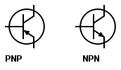
The first of our simple electronic breadboard projects is the transistor touch switch. Transistors come in two different varieties NPN and PNP. You can’t use either because they must be wired up differently.
The circuit diagram below shows an NPN transistor. You can tell this because the arrow on the emitter points out. The symbol for a PNP transistor is similar except the arrow points the other way round.

The transistor is off. As you touch the two wires your finger acts as a resistor. This allows current to flow into the base of the transistor and turn it on allowing current to flow from the collector and through the LED to illuminate it.
If you press your finger harder the resistance of your finger will lessen allowing more current to flow to the base. This will allow more current to flow from the collector and the LED will glow brighter. You can plug a couple of drawing pins into the breadboard and wire these up to become the touch terminals.
Simple electronic breadboard projects – The breadboard layout


The next of the simple electronic breadboard projects is called the flip-flop or more technically an astable multivibrator. Look at the circuit diagram below.

By deconstructing it you can see it’s basically two of the touch switch circuits. In the touch switch circuits, your finger acts as a resistor to turn the transistor on and light the LED. In this circuit, there is a 10K resistor in the same position so you can see that it will light the LED however as well as lighting the LED there is another connection from it that goes back to the base of the other transistor via a capacitor.
This turns the transistor off. As one of the capacitors charges, current flows in the base of the transistor turning it on and lighting the LED. When the capacitor becomes fully charged it stops the current flowing and so turns off the transistor. Then the other capacitor charges causing current to flow and turn that transistor on and thus light the other LED.
This continues so one LED lights then goes off as the other one lights then goes off. Larger value capacitors take longer to charge so the flashing speed is slower. By using lower value capacitors the speed of the flashing will be faster.
The breadboard layout.


Simple electronic breadboard projects – Final thoughts and the next stage
Once you start to build simple electronic breadboard projects you will start to get more experienced. Hopefully, these two simple examples will get you on your way. Once you start to get a grasp of circuit diagrams you will be able to take small circuits and then turn them into breadboard projects yourself.

If you want to progress to the next level, How to build a circuit on a breadboard has more tips to help you.
If you want to build more breadboard projects and maybe more complex ones have a read of my Best breadboard kit buyers guide. This contains some quite complex kits to build with everything included.
If you want to keep the circuit you’ve built on the breadboard, be sure to read my guide on Solderless breadboard to PCB. This contains information, what things you’ll need and some tips to help you.
Once you get used to building simple breadboard projects why not move on to something more complex? My article “Breadboard synthesizer” gives you full instructions and diagrams to help you build a complete synthesizer.
Also check out my post, Breadboards – the complete guide, for everything you need to know about breadboards.
Check out my guide about the easy way to test components.


“Hi, I’m Graham Moore and I’ve been building electronic projects since I was 12. I had a fascination for old radios and taking them to pieces but when my Nan bought me an electric soldering iron, I realised with a few components I could build stuff.
Learning to solder opened up many doors for me as electronics also became a career. I hope you get as much from it as i did”.
Breadboard design software

Breadboard design software tested and compared If you use breadboards, you might find breadboard design software helps with your building. Breadboards are tremendously useful for beginners who can’t solder…
Breadboard synthesizer

Breadboard synthesizer This breadboard synthesizer project was inspired by wanting to build something really good on a breadboard. There are plenty of breadboard projects for flashing lights and stuff like…
Breadboard tips

Breadboard tips I learnt to use breadboards in a sort of trial-and-error method. There doesn’t seem to be much in the way of instructions on how to use a breadboard….
Common breadboard mistakes

Common breadboard mistakes If your breadboard circuit doesn’t work don’t worry you are not the first and won’t be the last. Fortunately, there are a lot of common breadboard mistakes…
How are breadboards connected?

How are breadboards connected? Breadboards vary in type so how they are connected depends on the type of breadboard. Breadboards can be further divided into two main types and that’s…
Breadboard power supply

Choosing a Breadboard power supply When you use a breadboard you’re going to need a power supply. The power supply you use will depend on the circuit or project you…