

Testing an optoisolator or optocoupler.
There are a few methods of how to test an optoisolator. I’m going to concentrate on the 2 that I consider to be the best and easiest.
How to test an optoisolator using a component tester.
This is my preferred method
Advantages
You usually don’t need a circuit diagram or pin out of the device
It’s quick and easy
It’s fairly conclusive even for a beginner
Disadvantages
You have to remove the device from the circuit and you need a component tester
Ok I don’t consider the disadvantages to be that bad. Most of the time the optocoupler will be in a socket and even if it’s not, having 6 pins makes it about the easiest dual in line component to desolder. If you’re even slightly into the hobby of electronics getting one of these component testers is a no brainer. They are so easy to use, cheap and will save you no end of time and trouble. I really could not be without one now it’s defiantly one of the best purchases I’ve made in my hobby. If you’ve not seen them before you can read about them here.
So let’s test an optocoupler. First you need a little information if you don’t already know. Most optoisolators come as an 8 or 6 pin DIL device. There are some 4 pin ones as well and you can test those but you’ll find it easier with a pin out diagram although you can get by without one.
They are actually two components in an optocoupler, a component that generates light, the LED and the thing that sees the light, some sort of photo transistor. As these are packaged inside the device so you can’t actually see any light.
I’ve got a little piece of Vero board with a DIL socket and wires to connect it to the component tester.

I use a small piece of Veroboard and a DIL socket to connect up to the component tester.
If you have a 6 pin DIL device connect the 3 leads from the device pins 1, 2 and 3 to the component tester. If the device is working you’ll get an indication and a pin out diagram on the screen that you have a working LED. Then disconnect it and connect pins 4, 5 and 6 to the component tester. Again if the device is working you’ll get an indication that you have a working transistor or similar device. It’s as simple as that with 6 pin DIL opto isolators.

The component tester connected to the “transistor” part of the optoisolator.

The image above shows a popular 8 pin optoisolator the 6N138, inserted into the test rig so it can be easily connected to the component tester.
With an 8 pin opto isolator you’ll find it easier if you have a pin out diagram, you can find almost all of them on the internet. Even if you haven’t got one to hand, you can try the first 3 connections connected to the component tester and then try the last 3 connected to the component tester. You’re likely to get the component tester indicating that you have a diode and it will show you the connections on its screen.

In the picture above you can see pins 1,2 and 3 connected to the component tester. The test shows pins 2 and 3 are where the LED is and that its working and it shows various other readings about the LED and you can see it’s polarity.
Do the same with the connections on the other side of the device to check the transistor part of the optoisolator. Simple as that, if you get an “unrecognised component or damaged component” check everything is connected and try again.

In the picture above pins 5,6 and 7 are connected to the component tester and it indicates an NPN transistor and shows the emitter, base and collector connections.
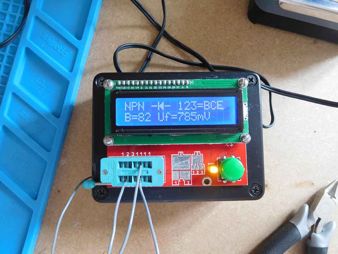
The picture above shows pins 6, 7 and 8 connected.
How to test an optocoupler in circuit
If you can’t take it out of the circuit you can use an oscilloscope.
Advantages
The advantage of this method is if the device is soldered onto a PCB you don’t have to desolder it to test it
Disadvantages
You need an oscilloscope
You need to know how the circuit works, so you’ll probably need a circuit diagram or at least a pin out diagram of the device such as what is making the optocoupler work at a particular time. It’s no use trying to read an output if nothing is going into it to make it work
Sometimes the results can be a little inconclusive to a beginner. Such as you can see some output but you’re not certain if it’s correct or at the right level, that kind of thing, as you don’t get a simple indication like you do with the component tester.
Although you need an oscilloscope you don’t need an all singing all dancing one. A simple cheap £20 device will work for this application as it will for many others. Read here for more information about cheap oscilloscopes.
I’ll describe how I test an optoisolator in a circuit so you’ll be able to adapt the instructions for your own test situation.
The device I’m testing is a 6N138 which is a popular optoisolator used in MIDI (Musical Instrument Digital Interface) applications. I’m using the Mutable Instrument Shruthi Synthesiser, like most synthesisers it has a MIDI interface which uses an optoisolator. If you look at the circuit diagram or a pin out of the 6N138 optoisolator you’ll see that the input to it is pin 2. You need to have the circuit powered up and have something generating a MIDI signal to be able to trace it through the circuit. I used the Mr.Midi 2 MIDI file player and plugged it into the Mutable Instrument Shruthi synthesiser MIDI input.

In the picture above you can just about make out that the DSO 138 oscilloscope is set to DC input and 1 volt per square.
Get you oscilloscope, I’m using the DSO 138, you can read more about it here. Set its input to DC and have 0V low down on the screen and set it so 5V is near the top. This makes it easy to see what’s going on.

In the picture above you can see the yellow line which is showing the probe on the output (pin 6) of the 6N138 being pulled high at about 5 volts, 5 squares above the 0 volt line. this is without any MIDI data going into the optoisolator.
You need to set the oscilloscope to a fairly high frequency for MIDI. The output of the 6N138 optoisolator is pin 6 and when you put the oscilloscope probe on pin 6 you will see the screen show that the signal is high at around 5V. This is what you would expect if you look at the Mutable Instruments Shruthi circuit diagram as the output has a pull up resistor.

The picture above shows the Mr.midi midi file player. This was used to generate MIDI signals to check the MIDI flow through the 6N138 optoisolator.
When I press start on the MIDI file player, MIDI information is sent to the input of the 6N138 optoisolator and the oscilloscope starts triggering, which you can see as the green LED on it flashes as the input goes high and low. The screen on the oscilloscope will also show you that there is the expected signal as the MIDI data goes through the optoisolator, a frequency indicator and pulse width reading will also show on the DSO 138 oscilloscope screen. When you press stop on the MIDI file player the signal stops and returns to “high”.
This shows a perfectly functioning 6N138 optoisolator without having to remove it from the circuit.

In the picture above you can see that the DSO 138 oscilloscope is showing the MIDI data at the output of the 6N138 optoisolator, the signal is switching between roughly 0 volts and 5 volts. The green trigger LED is flashing, although you can’t see this as the photo. This is while MIDI data is being sent. You can also see Freq, Cycle, PW and duty while the MIDI signal is present. As soon as the signal stops it returns to a flat line at 5 volts. This shows a fully working optoisolator with the MIDI data going through the input of the 6N138 optoisolator and appearing at the output pin 6.

Testing a 6N138 optoisolator in circuit using the DSO 138 oscilloscope.
How to test an opto isolator using a multimeter
Advantages
Most people can find a multimeter.
Disadvantages
You need to remove the device from the board.
You need to have a pin out diagram of the device.
It can be a bit fiddly to try to check it holding probes and reversing them and similarly to the above oscilloscope method for a beginner it can be a little inconclusive.
You basically have to use the multimeter to test the led and transistor by following the pin out of the device and try to hold the test leads and then reverse the connections.
I have to admit I like to consider myself more advanced than a beginner but when I came to test an optocoupler using me multimeter a was left scratching my head as to whether it was actually a good device or a faulty one. That’s not what you want; you want a conclusive yes or no. I wouldn’t bother trying to use a multimeter to test an opt isolator because of how difficult it is compared to the component tester or oscilloscope method.