

How to build a circuit on a breadboard
The advice here assumes that you are looking at how to build a circuit on a breadboard by working from a circuit diagram and not copying an existing breadboard layout.
There are a few things to bear in mind to make the job easier. If you have a simple circuit it’s relatively easy to just quickly plug components in without much afterthought but if you have a particularly complicated circuit it’s better in the long run to get used to doing things in a certain way from the start.
Some things seem fairly obvious but I’ll still mention them because what seems obvious to one person isn’t to another.
If you are a beginner when it comes to breadboards you may find my post, Breadboards – the complete guide, helpful.
Information
The modern plastic breadboard in use today, with .1-inch spacing holes was patented in 1971 by Ronald Portugal.
First steps
Most breadboards have blue and red markings on the side strips for power. Unless you have a very good reason it’s best to stick with the positive red negative blue system. Try to use the same system for wiring up the breadboard with red wiring for positive.
If your circuit has a positive and negative supply voltage with a 0V you will have to work out a system. I stick with the colours on the breadboard and use red for positive, blue for negative and black for 0V.
Although you can just reuse wires of the same length to make connections, if there are a lot of them you can make the layout tidier and easier to build up and make sense of by just using connections cut to the correct length and laid flat against the board as shown in the picture below.

When you consider how to build a circuit on a breadboard you have to take into consideration the size of the breadboard.
Don’t try to cram too much onto one. Some people are far too ambitious. If you need to you can always link two together. Some even have slots to enable them to fit together snuggly.
I always get a printout or copy of the circuit diagram on an A4 sheet. You can then use this to write on. I then position the ICs on the breadboard. Starting from the circuit diagram, going left to right and working from top to bottom. Once they are in place I link the two strips under the IC together. This is my 0V or ground connection.

How to build a circuit on a breadboard – ICs
Go around the pin numbers connecting any that go from 0V to this. I then go around it again linking any pins to the positive and negative lines.

From the above picture you can see row 9 is linked with a black wire. This is going to be a 0V connection.
It’s convenient to have a horizontal 0V row near an IC. This way any components that connect from an IC pin number can just connect horizontally to it. I connect the pins that are connected to the positive and negative rails to the ends a and j. This leaves more space for components around the IC.
Notice that because it’s a simple circuit I’ve just used reusable wires for speed of construction. If it was a more complex circuit I would have used the short direct wires flat on the breadboard as shown in the top picture.

Print off your circuit diagram
Every time I complete a connection I use a luminous highlighter pen and draw on the circuit diagram. This way I can see it’s done.
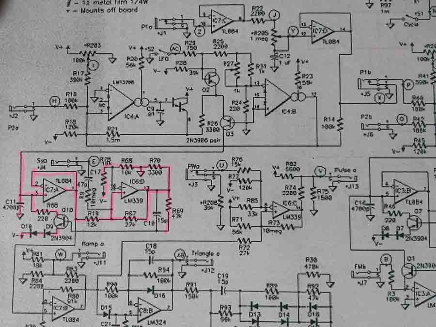
I then work around the IC looking for any pins that connect to 0v, positive or negative via a resistor and put those in. Then the same with capacitors, not forgetting to highlight them on the circuit diagram. I then move on to any subsequent ICs and do the same procedure.

As you can see from the picture above pin 2 is connected via a resistor to the positive supply. Pin 1 is connected to a capacitor that goes to 0V and pin 6 goes to a 0V via a resistor. You can create more 0V rows but don’t forget to connect them all up. This is where the highlighter on the circuit will help you.
It’s good to have a technique and stick with it as it makes construction a lot quicker. I’ve seen some people staring blankly not knowing where to start.
Once you’ve completed the method above you should have a fair amount of the circuit completed. You will also be able to clearly see which connections and components you still have to do.

Transistors can be plugged in as shown in the picture above.
If you are unsure of the pinouts I can highly recommend the KKmoon Multifunctional Transistor Tester DIY Kit Resistor Capacitor Triode Electronic Measurement with Acrylic Shell and Parts Set. There is a review of the device here.
Final thoughts on How to build a circuit on a breadboard
When it comes to how to build a circuit on a breadboard, this guide will hopefully point you in the right direction to be able to start constructing successful circuits.
If you want to make your circuit permanent by transferring it to a PCB be sure to check out my guide to Solderless breadboard to PCB for help, advice and some tips.
If your circuit doesn’t work have a look at my article on Common Breadboard mistakes so you can get yours working.
Finally, if you are looking for an impressive breadboard project to build check out my article on “Breadboard synthesizer”. This gives you detailed instructions and diagrams showing you how to build a complete synthesizer on a breadboard.


“Hi, I’m Graham Moore and I’ve been building electronic projects since I was 12. I had a fascination for old radios and taking them to pieces but when my Nan bought me an electric soldering iron, I realised with a few components I could build stuff.
Learning to solder opened up many doors for me as electronics also became a career. I hope you get as much from it as i did”.


