

Transferring a circuit diagram to a breadboard
What is a circuit diagram?
Transferring a circuit diagram to a breadboard can be straightforward if you follow simple steps.
A circuit diagram is a drawing of components and how they fit together, a bit like a map. An electronic component may connect to more than one other component and this is indicated by something called a node.

When you build an electronic circuit from a diagram you have to connect all the components exactly as the circuit diagram indicates. Complete all the connections and you have a working circuit. It’s that simple. It’s the same again when transferring a circuit diagram to a breadboard.
What is a solderless breadboard?
A solderless breadboard is a base for building electronic circuits. It is designed to make the construction of an electronic circuit as simple as possible. It is basically a lot of holes that have connections between them so components and wires can be quickly plugged in and quickly unplugged if necessary.

This is what makes a breadboard so useful for beginners in electronics. Don’t underestimate how useful they are though because they are very popular for electronic enthusiasts who have long passed the beginner stage. Very Experienced people still use them for trying out ideas and designs in the prototype stage.
The most common type of solderless breadboard is designed with rows of holes split down the middle. This is perfect for plugging in integrated circuits, you then have 4 holes on either side of the IC. Running up and down at the ends of the breadboard are columns for positive and negative already marked for the power supplies.
Information
The modern plastic breadboard in use today, with .1-inch spacing holes was patented in 1971 by Ronald Portugal.
How do you read the circuit diagram?
The easiest way to explain how to read a circuit diagram is to take an example and go through it starting with the very basics.
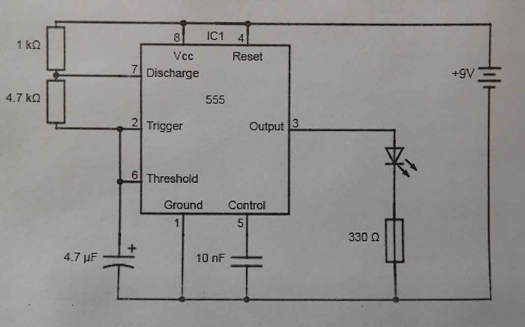
First I’ve printed off the circuit onto a sheet of paper so it’s handy to look at and write on. It’s a simple circuit that will flash a light-emitting diode or LED.
What are the circuit diagram symbols?
First, you need to know what the symbols are.
Integrated circuit or IC
The big square in the middle with all the numbers around it is an integrated circuit or IC. In this case, it is something that is known as a 555 timer.

Resistor
The oblong symbol is a resistor with the value of 1K ohms.

Here is another resistor. This time 4.7K value, which is sometimes written as 4K7. Oblongs like these are fixed resistors of the value next to them on a circuit diagram.

Capacitor
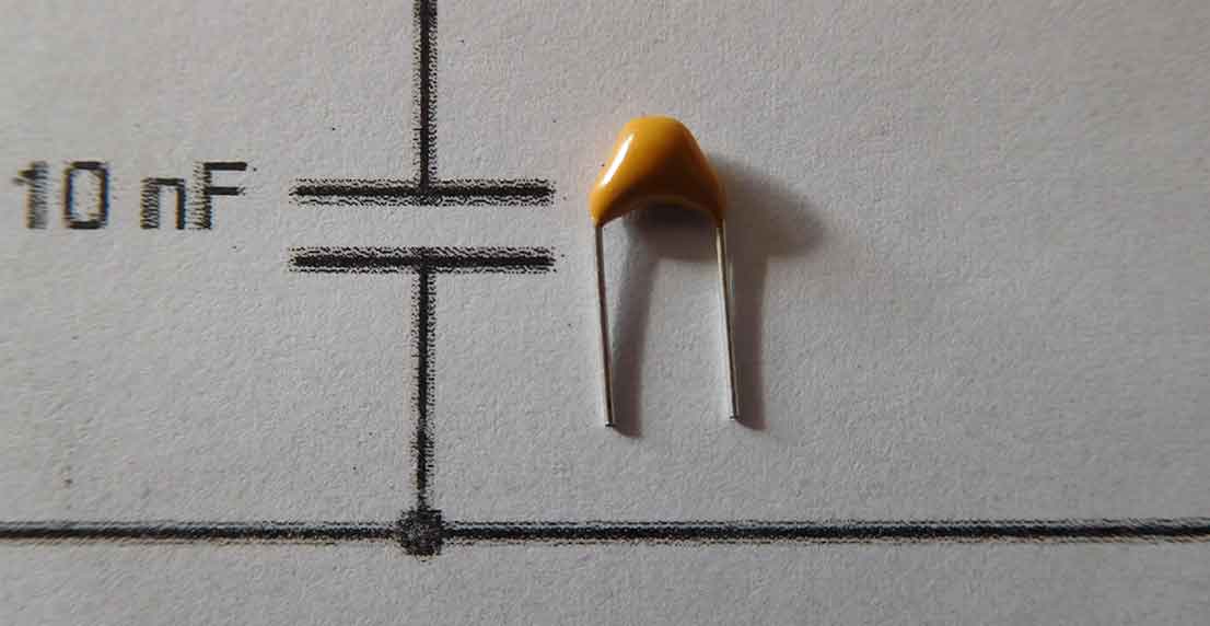
A capacitor symbol is two parallel lines, the one below is 10nF or 10 nano Farads.
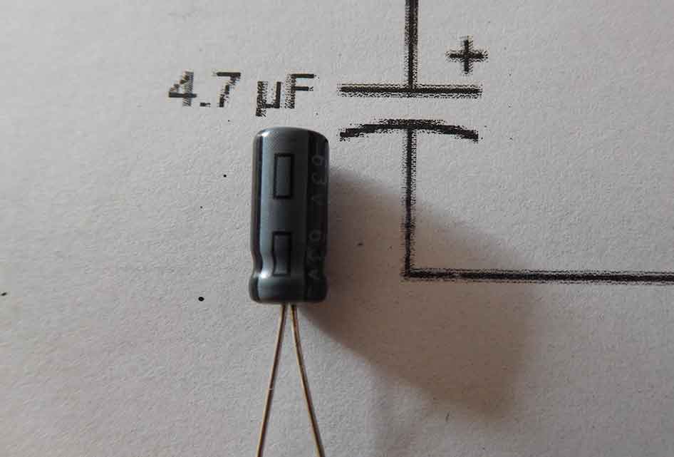
This is another capacitor but the bottom line is curved. This is a polarised capacitor and it’s important to connect it the correct way around. On the circuit diagram symbol, the straight line has a + symbol to show this is the positive connection. The actual component, which is a 4.7 uF capacitor has a negative mark on the case.
Light emitting diode or LED
The component and symbol below is a light-emitting diode or LED. This component also has to be connected the correct way around. The triangle on the symbol points to the cathode. The back of the triangle is the anode. This also has a longer lead on the component.

Battery
The last symbol on the circuit diagram is the battery shown here with a battery clip. The long line on the symbol is the positive and the short line is the negative.
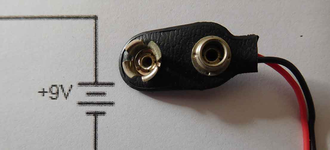
That’s all the symbols on this circuit explained. The only other component is the other resistor next to the LED but you now know what a resistor is. You are now ready to start transferring a circuit diagram to a breadboard.

Shown above is the circuit diagram and the components next to their symbols. Now you know the components on the circuit diagram. How do they connect up?
The lines between the symbols
Although the 555 timer has 8 pins around the outside the diagram doesn’t draw it like that. The diagram has the numbers to make the drawing simpler and easier to read.
If you look at pin 3 of the IC it just goes to the LED and the other side of the LED just connects to the 330R resistor.
Other components have more connections. From the diagram above you can see that the positive connection of the 4u7F capacitor also connects to pins 2 and 6 of the 555 timer IC and one leg of the 4K7 resistor.
The circuit diagram shows you not only the components but also how they interconnect with each other.

Building it on the solderless breadboard
The solderless breadboard has four lines running up and down the sides of the board. These are shown with red and blue lines with a + and – above them. These are used for the power connections. In this case the battery, however, they don’t connect to each other.
This is a common mistake beginners make with breadboards. If you don’t link the power lines you won’t get power on the side the battery isn’t plugged into!
For other common mistakes on breadboards check out my post. You can work though if your circuit doesn’t work.

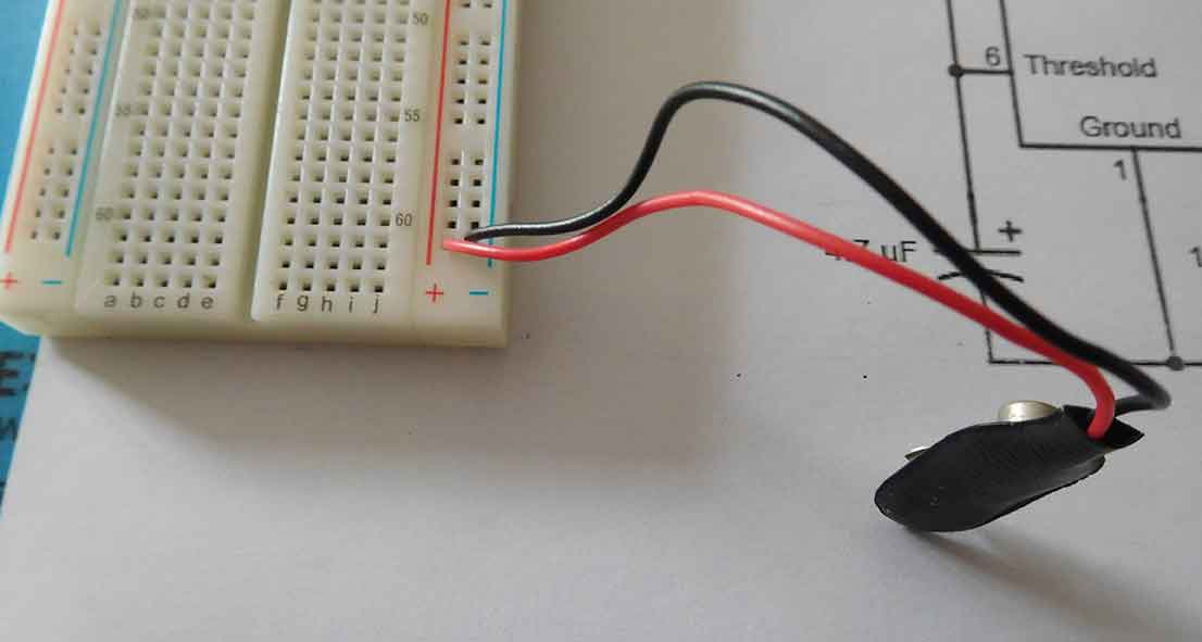
With the battery plugged into the bottom and the power links on the top, all the red and blue lines can now be used for power. In our case, 9V will be on all the red and blue holes.
I usually put the battery in the bottom right and the links on the top just to keep that wiring out of the way and leave the middle free for the circuit. Don’t connect the battery to the clips at this stage.
The order of components
Plug the 555 timer IC into the breadboard, down the centre of the board on either side of the middle line. The numbers around the outside are the pin numbers. The circle indent shows where pin 1 is. A half-circle indent at the top of the chip is also commonly used to show pin 1.
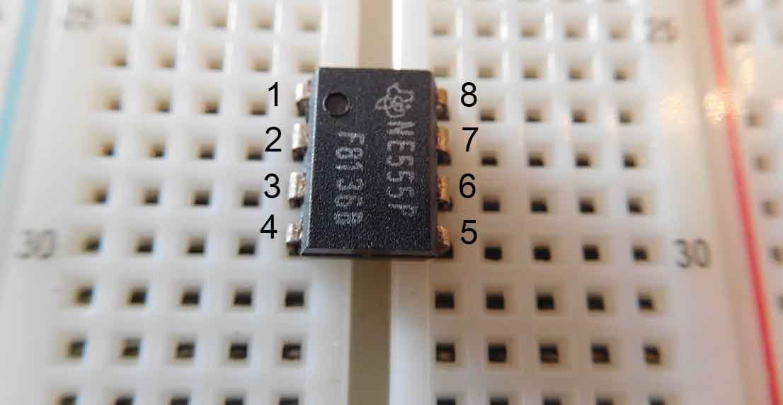
If you look at the circuit diagram, pin 1 of the IC connects to the negative supply so you can make this connection with a wire from the line that pin 1 plugs into and the blue line as shown in the picture below.

Highlight the circuit diagram
When I’ve physically plugged in the lead to make that particular connection, I highlight that connection on the circuit diagram as shown in the picture below.

From the diagram, you can now clearly see that there are 3 other components to connect to the negative line.
You can also see that pin 8 and pin 4 from the IC connected to the positive line. Those are the ones I’ll do next using red wires this time.

Transferring a circuit diagram to a breadboard – Tidy the connections
It’s more tidy to connect pin 4 to the left red line and pin 8 to the right red line. There is no difference electrically it just means fewer wires crossing the board. Notice that I also use the outermost connection. Any of the lines could be used but I use the nearest to the power line. It also leaves more space around the IC for the other components and connections.
Looking at the circuit diagram you can see that the 10nF capacitor connects to pin 5 of the IC with the other end connecting to the negative line. So plug the capacitor into pin 5. The other leg plugs into the line two rows down. Plug a black lead into that row and the other end goes into the negative line. Again use the right-hand one for convenience. This is shown in the picture below. After each connection highlight it on the circuit diagram.

looking at the circuit diagram again you can see that the 1K resistor connects to the IC pin 7 while the other end goes to the positive column.

The picture above shows the 1K resistor plugged in.
Keep connecting and highlighting
From the circuit diagram, you can see the 4K7 resistor connects between pin 2 and pin 7 of the IC. The picture below shows it in place. It’s raised up slightly so it doesn’t touch the other resistor. Once you’ve plugged it into the breadboard highlight the connection on the circuit diagram.

The 4u7F capacitor connects to pin 6 and the negative supply. This component is polarised meaning it has to be connected the correct way round. Look down the side of the capacitor. It has a line showing the negative lead. This has to go to the negative column on the breadboard with the positive lead of the capacitor going to pin 6 as is shown on the circuit diagram.

Keep highlighting the connections on the circuit diagram as you make them and you should have something like the picture below.
Don’t miss any connection

If you look at the circuit diagram, notice a connection between pins 2 and 6. Things like this can be easily missed when you’re trying to get a circuit together quickly. That’s why I use a paper printout and a highlighter.

The connection between pins 2 and 6 is made with a yellow cable.
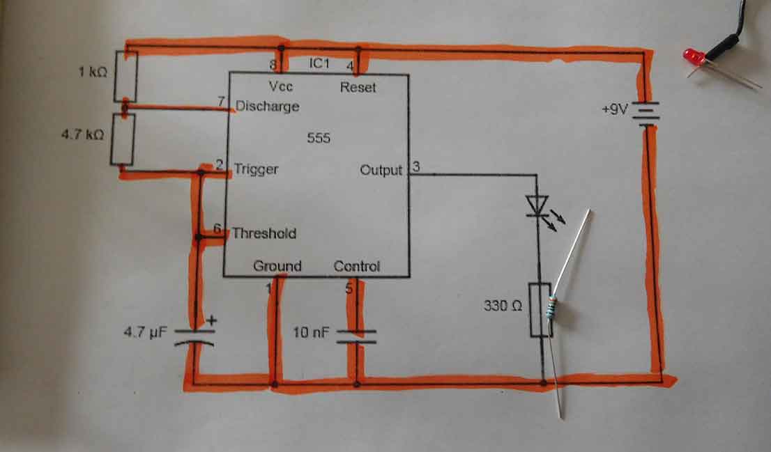
Once this is highlighted you can see the only components left are the LED and the 330R resistor to limit the brightness of it.
Transferring a circuit diagram to a breadboard – Component orientation
If you remember way back to the beginning of the article the LED has to be the correct way round otherwise it won’t light. So that’s the longest lead, the anode connecting to pin 3. You have to bend the legs a bit so the short leg can plug into the row under the IC. Then plug the 330R resistor into that row and the other end to the negative column, as indicated by the circuit diagram.
You will now have transferred the circuit diagram to a breadboard. Double-check the connections just to make sure none of the component wires are touching and you are ready to connect the battery to the clips.

If you haven’t made any mistakes you will have a flashing LED like in the picture above. You will also notice that the LED flashes very quickly, almost like a flicker it’s so fast.
Transferring a circuit diagram to a breadboard – How does it work?
Once you have built a circuit you’ll want to know how it works and how you can alter things to make it work differently. The 4K7 resistor and the 4u7F capacitor control how fast the LED flashes. Increasing the values of either of them will slow it down. Try out a 22Kor 47K resistor in place of the 4K7 one and the LED will flash slower.
That’s one of the advantages of transferring a circuit diagram onto a breadboard and not going straight to soldering it on a stripboard. You can quickly swap a component value without having to desolder it.
Many people struggle with desoldering components. It’s not that hard with a bit of practice and the right tools and techniques. Have a look at my guide to desoldering for some instructions and tips.

Transferring a circuit diagram to a breadboard – Final thoughts
If this is your first attempt at transferring a circuit diagram to a breadboard, then hopefully it worked OK and you will now be more knowledgeable. Once you know the basics it’s a question of getting more confident and checking everything carefully. Before you know it you’ll be building larger circuits and altering things. That’s the fun of constructing electronic circuits.
When you’ve built and played around with a few breadboard circuits you’ll get one you’ll want to keep and make more permanent. That’s when you need my next article transferring a breadboard to a printed circuit board or PCB.
Also check out my post, Breadboards – the complete guide, for everything you need to know about breadboards.


“Hi, I’m Graham Moore and I’ve been building electronic projects since I was 12. I had a fascination for old radios and taking them to pieces but when my Nan bought me an electric soldering iron, I realised with a few components I could build stuff.
Learning to solder opened up many doors for me as electronics also became a career. I hope you get as much from it as i did”.


