
Building a veroboard synthesiser voltage controlled oscillator
Ok so now the power supply is built it’s time to move on. I figured out the next thing is building a veroboard synthesiser voltage controlled oscillator. I’ve got the power supply to operate it and I guess it’s one of the things that’s more of a stand-alone item and easy to test.
I was going to try and come up with a design of my own but that could take years. Also, there are so many circuits floating around the web it seems a waste of time. Then there’s the fact that the guys that have designed these circuits are way better than me. There are better designs than I could ever hope to achieve, so that’s my mind made up.
Information
The standard .1 inch spacing Stripboard was invented around 1959. It’s still used today because of its versatility.
Then I just have to decide which is going to be the best one for the job.
I need it to be good, meaning there’s no point in building something that’s known to be problematic with tuning etc. I’ve read on one forum from a guy trying to get something going that he’s built. An expert had commented on the design saying that it was never going to be able to be tuned correctly for more than a couple of octaves. Also, given the component values, it would never go higher than 1khz!
No difficult to get parts. There seems no point in trying to build designs that use hard-to-find parts. I want to be able to get components for years to come so if I’m struggling now it will be impossible to find soon things like Curtis CEM ICs.
Building a veroboard synthesiser voltage controlled oscillator – Design
If I can I want to be able to lay the circuit out on Vero board so I’ve not got to try and track down a PCB. That also precludes designs that are overly complicated with loads of components.
I want to be able to get something up and running but also be able to upgrade it in the future. It seems that the best way to build a VCO is to use matched transistors and a thermal resister touching the two in thermal contact. There doesn’t seem to be any other way for it to reliably stay in tune. So at least I can use two unmatched transistors and a normal resistor to check it is working and then match transistors and try to get a thermal resistor later.
After weeks of research, I have found the perfect answer. The Thomas Henry 555 VCO. He’s well respected in synth module designs and even he states he is particularly proud of this design as he was trying to come up with something similar to a CEM3340 type of oscillator.
Incidentally, the CEM3340 was also used in the VCOs of the Sequential Circuits Pro 1 synthesiser.
Information
The Sequential Circuits Pro 1 was used for lots of the sounds on the Yazoo – Upstairs at Eric’s album.
Vince Clarke says it is his favourite synthesiser of all time
I always thought the oscillators on my Electronics and Music Maker Spectrum synthesizer to be among the best analogue voltage-controlled oscillators so I’m looking forward to building and testing these. Also, the component list looks great with only commonly available parts called for.
The Layout

The VCO board with printed layout, with wire links and IC sockets mounted.
After playing around with layouts I’ve decided that the best way is to mount the exponential generator and matched transistors on separate small Veroboards as I’ve already been playing around with this part of the circuit and got a few already working on the smallest sized Veroboard and I’ve got loads more of these to use up so each voltage input will be built on its own bard.
Information
Where would electronics be without soldering? Unbelievably, the modern soldering iron was patented way back in 1896 by Richard Schneider and August Tinnerhol and was known as an “Electric heating apparatus”.
I can then fit two VCOs on one large Veroboard that I’ve been using. I bought a pack of 10 of them extremely cheaply and I mean extremely, I paid less than three pounds for eight boards.
For more information check my article What’s the best stripboard?
I’m going to build 8 VCOs and so use 8 small Veroboards and four of the large Veroboard. So that will mean 8 VCOs without having to spend anything on the actually board material.
I’m building 8 because I’ve noticed in some of the comments that you can switch in a capacitor and make it into a voltage-controlled low-frequency oscillator. So no messing around with a separate design for that. It will lead to a very flexible configuration, 8 VCOs or 1 VCO and 7 VC LFOs and everything in between. Making the modular even more versatile.
VCO exponential generators
The layout for the exponential converter is fairly simple there are a few cuts to make on the Veroboard and only a few components to solder on.

The exponential generator is built on a small veroboard. Notice the thermal resistor mounted over the top of the two matched resistors.
The board that the two oscillators are built on is quite large. One thing I noticed was that there were a few track shorts where there shouldn’t have been! You need to get a magnifier on it and check and it’s always easier to do this before you start soldering parts on to it.
If you are new to using veroboard or want some more information I have several articles that might help with construction.
VCO Veroboard layout
To make things easier still you can partially build each oscillator and check it works before you fully populate the board. I’ve looked at the circuit and it can be stripped down to the triangle wave oscillator. The other waves are derived from it so you can just get that working first which is how I did the first board.
The others I just fully populated in the normal order of wire links IC sockets and then resistors. Finally, the ICs were inserted into their sockets and the variable resistors that would be panel mounted.

The picture above shows the VCO board fully populated with all the board-mounted components.
The component overlay of the VCO.

This is the printout I used to stick on the veroboard.
Each one was powered up and tested. Seven of the eight worked the first time which was a bit of a result. The eighth had an op-amp inserted the wrong way around.
After I had made the synthesiser front panels (you can read about that here) I fitted the variable resistors, sockets and switches. I then did the wiring between the panel components and then between them and the circuit boards. The next stage was to wire everything up to the power supply.

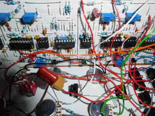
The boards are mounted and wired up to the front panel controls. I must admit to not realising how complex and messy this would all become.
The final bit was to tune the VCO’s. This can be done in quite a few ways so I decided to do a separate article on the calibration of VCOs that you can read here.
Building a veroboard synthesiser voltage controlled oscillator – An unforeseen problem
While at this stage I noticed that the stability wasn’t as good as I was expecting. I thought this may be due to several things.

4 VCO’s being tested with an oscilloscope.
- Maybe the timing capacitor wasn’t as good as I’d hoped.
- Maybe the wiring to the capacitor and switch lowering the frequency to that of an LFO was affecting the pitch.
- Maybe having a separate board for the exponential converter and fairly long wires was the problem.
- Maybe the problem was the power supply, maybe it wasn’t smooth enough.
These were all the reasons I thought of to investigate so firstly I’d look at the power supply. I disconnected all the VCOs and just powered one board. To my surprise, this proved to be the problem. With one board the VCO’s pitch was rock solid. If I connected another board the pitch varied, in fact, it was all over the place.
I experimented by moving and adding decoupling capacitors. Then increase the values and put twenty ohm resistors on the supply of each oscillator. Nothing improved the stability. In the end, I decided to just use a separate power supply for each oscillator board.
I noticed that the Yusynth VCO power supply has separate 78L15 and 79L15 regulators on the board. Maybe that’s just the best way to do it. In any event, it had taken me loads of time experimenting without any real progress so it was easy to just make three more power supplies.
Building a veroboard synthesiser voltage controlled oscillator – Final thoughts
So that’s how they are going to end up. Eight VCO’s switchable to LFO’s with four separate power supplies. Now it’s time to think about the filters.
You can find links to stuff you might find useful here at Veroboard and Stripboard resources, tools and stuff.
If you have any interest at all in the subject of stripboards (which I’m guessing you do) then have a look at my post, Stripboards – the Complete Guide. I’m sure you’ll pick up a few things to save you money of make the way you use stripboard easier.


“Hi, I’m Graham Moore and I’ve been building electronic projects since I was 12. I had a fascination for old radios and taking them to pieces but when my Nan bought me an electric soldering iron, I realised with a few components I could build stuff.
Learning to solder opened up many doors for me as electronics also became a career. I hope you get as much from it as i did”.
Common stripboard mistakes

Common stripboard mistakes There’s nothing more frustrating than completing a circuit on a stripboard only to find out it doesn’t work. OK, there are other things but it’s still pretty…
What’s the best stripboard?

Stripboard has been around for a long time and its still manufactured and bought in large quantities. It has, and will still remain hugely useful for electronic hobbyists to build,…
Veroboard and Stripboard resources, tools and stuff
Veroboard and Stripboard resources, tools and stuff The products and tools listed here are for the various articles relating to Veroboard and Stripboard. I have an article if you want…
Lochmaster 4.0

Lochmaster 4.0, is it the best stripboard layout software? I have tried a few of the other available stripboard layout designer software packages. There is some very good free software…