

Stripboard CEM3340 VCO
If you’re looking for a stripboard CEM3340 VCO design this is probably for you. The CEM3340 or its AS3340 equivalent has two main advantages over many other VCO designs.
Firstly it doesn’t require a temperature coefficient resistor. This attempts to compensate for the pitch change with temperature that occurs with VCOs.
They aren’t easy to come by and they make construction more difficult as they really need to be mounted over the top of transistors and coated in epoxy adhesive to work properly. Secondly, it doesn’t need the traditional two-matched resistors working as an exponential converter.
All this is taken care of by the CEM3340 for you. This is all excellent and makes things much easier for the constructor and the quality of the finished voltage-controlled oscillator.

Stripboard CEM3340 VCO – Stripboard layout details

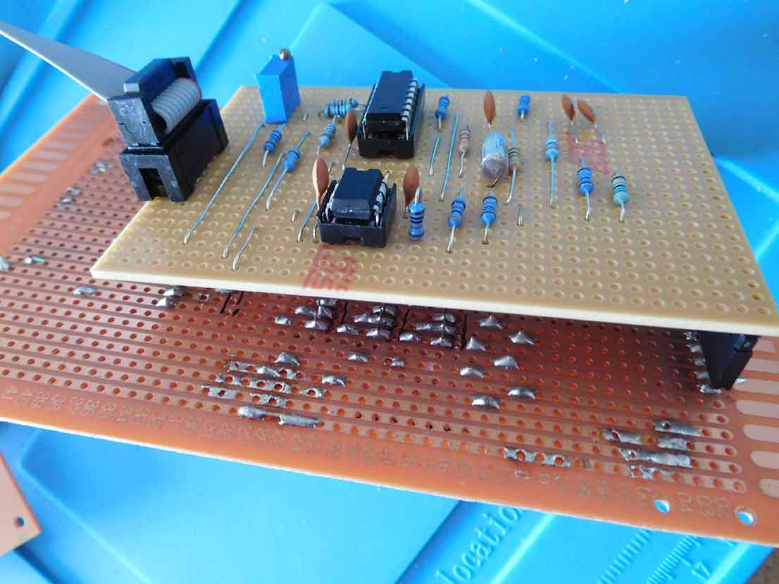
I decided to build this CEM33340 stripboard on two separate strip boards. Why I hear you ask. Well, it’s mainly to make the construction easier. I’ve done it in a way that many designers of Eurorack synthesizers have done because I think it’s the best way. I’ve seen it done in years of building and looking at different designs.
By using two strip boards you can make the boards physically smaller so you can fit them into a Eurorack design if that’s ultimately what you want to do.
It saves on an awful lot of wiring connecting up potentiometers, switches and sockets to the board. It also saves having to mount the component PCB to the panel. This means you don’t have to fabricate brackets or drill mounting holes on the front panel.
The sockets and connectors double as a way of holding the PCB and wiring and you can plug and unplug it. This is a definite advantage when you want to make repairs or upgrades to the circuit.
I’ve also used the Eurorack way of powering circuits. It makes it easy to remove a board as you can just unplug the power from it without any de-soldering.
If you are wondering how the diagrams are produced it’s by using the Lochmaster design software. It certainly helps when it comes to designing on a Stripboard. you don’t have to use graph paper and an eraser.

Power checking board
I always check what’s coming out of a euro rack ribbon cable before I plug it in to power a board. It puts my mind at rest before a new circuit goes up in smoke. Just to confirm the sockets are the right way around. The leads the right way around and there’s a plus and minus supply.
Let’s be honest it’s all too easy to solder a socket in backwards or get the plug the wrong way around on the ribbon cable. Some Eurorack designs do have protection diodes on the boards to stop damage from an inverted supply but I think it’s better not to connect the power up the wrong way at all, regardless of protection.
I used to do this with a multimeter but having to find a diagram because I could never remember with enough confidence, became a chore after a few boards.
I built a simple stripboard tester with a couple of resistors and a red and green LED to indicate the +12V and the -12V. All I have to do is plug the end of the powered euro rack ribbon cable into the socket. If the red and green LEDs light I know it’s OK to plug into the board.
Stripboard CEM3340 VCO circuit
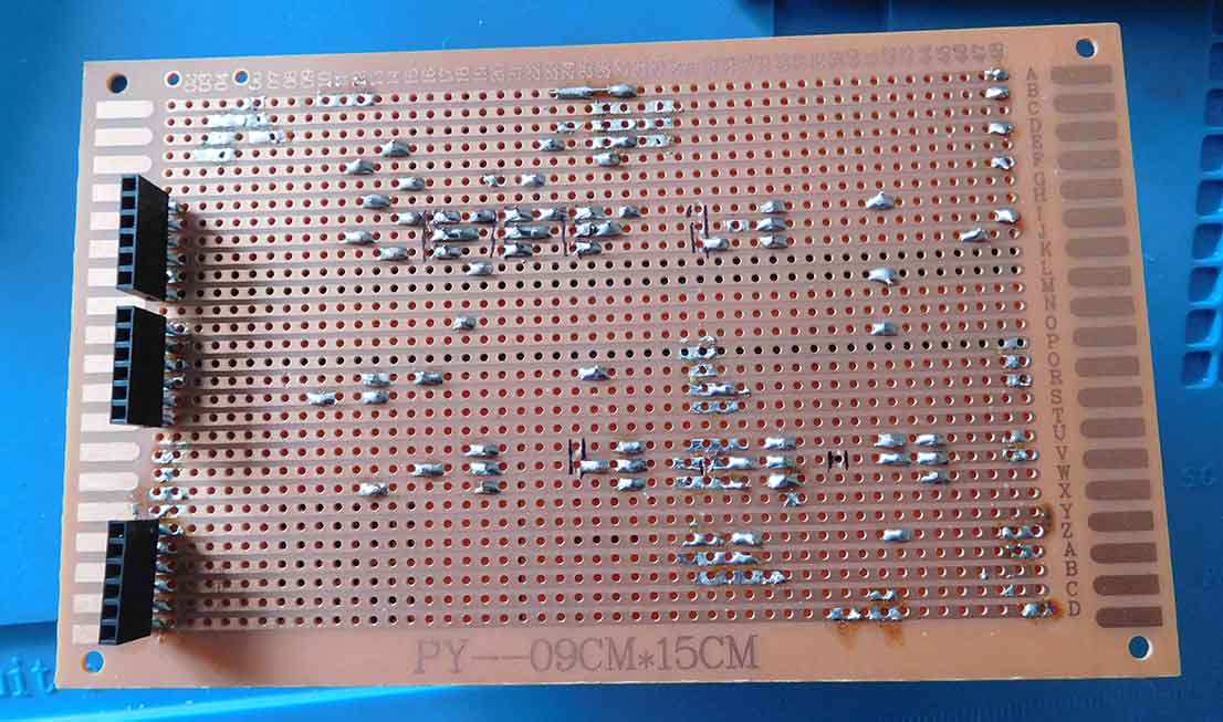

Tip – Always use IC sockets
The cost is minuscule compared to the ICs and there’s no easier way to check if an IC is working.
You just unplug it from a socket and plug it into another one.
This design is similar to the voltage-controlled oscillator circuits for the Sequential Circuits Pro 1 synthesizer. I’ve built the circuit on the breadboard first to test it out you can see that on my Breadboad CEM3340 circuit design article.
The pulse width can be changed manually with the potentiometer or automatically via a control voltage. This is through the modulation input which also has an amount control to tweak the modulation depth.
Each of the three waveforms, triangle, pulse and saw tooth has a switch to select any or all of them at one time.
As of the time of writing this post, I haven’t included any form of synchronisation input. There are ways to have soft or hard synchronisation and there is a design I particularly liked on my old Electronics and Music Maker Spectrum synthesizer. This synthesizer also had CEM3340 Curtis Electromusic ICs at the heart of its oscillators.
It also had a clever circuit for oscillator synchronisation which had a variable resistor rather than an on-off switch. This could produce loads of brilliant sounds from the oscillator circuits. It was much more versatile than the standard way and there must be a way of incorporating voltage control of the synchronisation amount. This is something I will definitely play around with in the future.
Stripboard CEM3340 VCO – Circuit connections
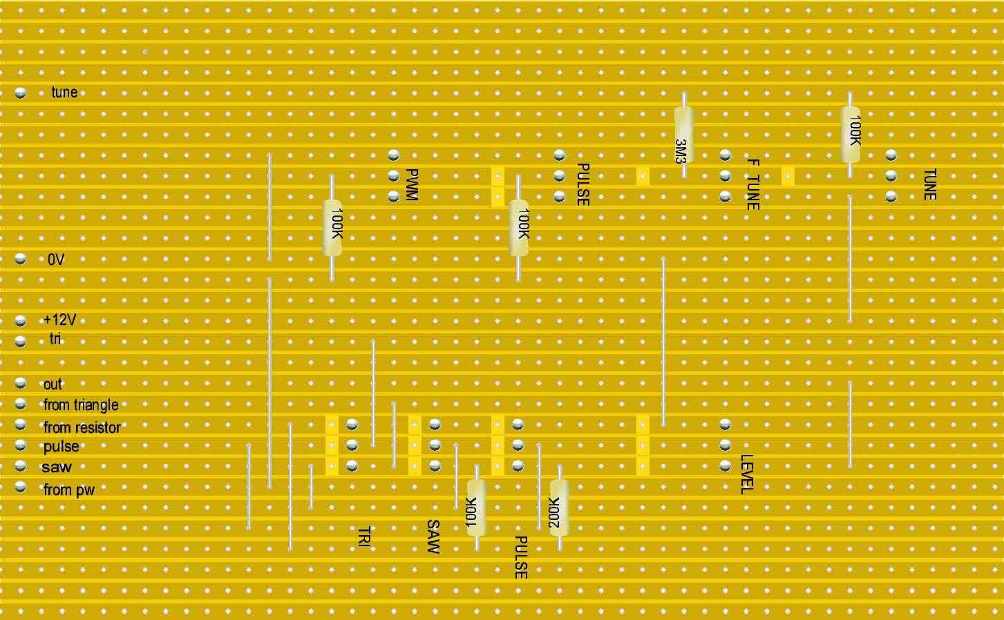
I’ve used the SIL (single in-line) female connectors so gold strip pins plug into them. I also used a larger stripboard layout for the front panel controls. This was more a way to cheaply and quickly get the circuit working. In the future, I may use a smaller board and alter the positions of the switches, potentiometers and sockets to make a euro rack layout and front panel.
If you take 0V and 12V to the front panel stripboard it takes care of a lot of connections to the potentiometers. There are also some other wiring and components that it just makes sense to have on this stripboard.


Final thoughts on stripboard CEM3340 VCO
The CEM3340 IC is made for electronic music applications and with the AS3340 compatible now being available at around £5 you can make a very reasonably priced VCO for your synthesizer. This is also one of the most accurate and temperature-stable voltage-controlled oscillators that I have built.
It is also possible to add another preset resistor to calibrate the high-frequency tracking. It’s common for VCOs to have this adjustment as some oscillators go a bit non-linear at their top end. Initially, I had this preset on the breadboard layout. I later found I didn’t need it so I left it out of the stripboard layout.
If you find you need it, it’s pretty easy to add if you check out the datasheet.
If you have even the slightest interest in things stripboard-related then check out my post, Stripboards – the complete guide. I’m sure you’ll pick up at least one tip to save you time or money!


“Hi, I’m Graham Moore and I’ve been building electronic projects since I was 12. I had a fascination for old radios and taking them to pieces but when my Nan bought me an electric soldering iron, I realised with a few components I could build stuff.
Learning to solder opened up many doors for me as electronics also became a career. I hope you get as much from it as i did”.
Hide Ads for Premium Members
[quads_disable_ads_form]
555 monostable calculator

555 monostable calculator Download the 555 monostable calculator to easily work out the time from the components. Once you have downloaded the spreadsheet, all you have to do is input…
555 astable calculator

555 astable calculator Click further down the page for a downloadable 555 astable calculator. If you’ve joined this guide from the 555 operating modes page or even if you haven’t,…
555 timer modes

555 timer modes The 555 timer has 3 main modes of operation. These three 555 timer modes are astable, monostable and bistable. You can achieve each of the modes by…
How to test a 555 timer

How to test a 555 timer This guide will show you how to test a 555 timer. I’ve covered testing many types of electronic components before and this tends to…
Capacitor value codes

Capacitor value codes Capacitor value codes are often used to indicate the value of a capacitor. Whereas resistors have usually stuck to a standard colour code (well standard-ish as it…
Lite windows with DAWs

Lite Windows with DAWs I wondered how much performance boost I’d get using Lite Windows with DAWs. The test results were shocking! A few years ago I decided to use…
How to connect Kodi to a network drive

How to connect Kodi to a network drive If you need to know how to connect Kodi to a network drive, it will depend on your particular network drive. I’m…
Can you solder without flux?

Can you solder without flux? The simple answer to can you solder without flux is no. The good news is that if you have got some solder it’s more than…