

Building a Breadboard voltage-controlled oscillator project
This breadboard voltage-controlled oscillator project uses the CEM3340 Curtis Electro music IC or one of its equivalents. I have actually used an equivalent, the AS3340 from Thonk.co.uk.
I don’t know why but there seems to be some snobbery about using this IC when building a voltage-controlled oscillator for a synthesizer. As though if you use it it’s cheating? Why, it’s manufactured to be used, electronics is hard enough as it is. For me it’s like saying I’m going to build a car but not use wheels because they make it too easy.
Cleared that up then, I’m using the AS3340 because it’s excellent and you don’t need to use two matched transistors together as an exponential generator. Also, you don’t have to use a temperature-compensating resistor.
Information
The Sequential Circuits Pro 1 was used for lots of the sounds on the Yazoo – Upstairs at Eric’s album.
Vince Clarke says it is his favourite synthesiser of all time.
The way I’m going to show you how to build this circuit is to build the “core” of the voltage controlled oscillator first using a minimum of components and then test that its working correctly before you add other functions to it. It can become very hard to track down errors in a complex breadboard circuit. This method means you can dissemble back to the last working stage if you have problems.
If you are a breadboard beginner check out my article “Breadboard tips”. You may even pick up a helpful tip or two if you have a lot of experience.
Also check out my post, Breadboards – the complete guide, for everything you need to know about breadboards.

Constructing the breadboard voltage-controlled oscillator project
I’ve used the red rails for +12V and the blue rails for 0V.
When making links you can use tinned copper wire for the shorter ones but when they are longer use insulated wire otherwise you’ll end up with bare wires touching each other. I’ve listed all the connections and if you follow them in order the smallest parts get inserted first as it’s harder to get them plugged in properly when larger components are nearby.
For some reason Fritzing the software I use to generate the colour diagrams doesn’t show some values of resistors correctly. I’ve noticed the 3M3 value shows as orange, orange, black when it should be orange, orange, green. Some of the other larger values over 1M are shown incorrectly. So use the values that I specify in the text and if you need to double check the colour code check my article Resistor colour codes.

Parts list for the breadboard voltage-controlled oscillator project
If you are building this project as an experiment I wouldn’t worry too much about the resistors or capacitors. You can just use cheap 5% carbon resistors and whatever capacitors you can find however if you intend to use it more seriously for musical synthesizer applications I would use 1% metal film resistors and a good quality multi-turn preset will make tuning it easier.
Also, the 1000pF capacitor should be a good quality one like polystyrene. It will work with any 1000pF capacitor but the frequency may drift off as the temperature changes. This will make it difficult to tune properly for serious musical use. Even if you do manage to tune it, it will probably drift in time. It’s just better to use a good quality one if you can get it.
Breadboard and wire for links
620R resistor
5K6 resistor
24K resistor
1K8 resistor
1M5 resistor
360K resistor
470R resistor x 2
100K resistor
10K preset (multi turn)
100K potentiometer (linear)
100nF capacitor ceramic x 2
10nF capacitor ceramic x 2
1000pF capacitor polystyrene
CEM3340 or equivalent such as AS3340
Components for fine tune control
3M3 resistor
100K potentiometer
Components for pulse width control and modulation
470K resistor
100K resistor x 2
100nF capacitor x 2
100K potentiometer (linear) x 2
TL072 Op amp
Components for waveforms and output level
4 x 100K resistor
33K resistor
10K resistor
560K resistor
200K resistor
3 x Switch
100K potentiometer
Incidentally don’t just follow the instructions like painting by numbers. Print off the circuit diagrams and highlight each connection on the circuit diagram as you make it on the breadboard. You’ll learn much more by doing it this way.

This is the basic circuit diagram of the VCO.
Step-by-step instructions
1. Link 16j to +red
2. Link 20j to -blue
3. Link 24j to -blue
4. Link 18b to 12b
5. Link 14j to -blue
6. Link the two blue rails together at the bottom
7. Link the two red rails together at the bottom
8. 620R resistor 18d to 24d
9. 5K6 resistor 12c to 17c
10. 24K resistor 11d to 16d
11. 1K8 resistor 18j to -blue
12. 1M5 resistor 19i to +red
13. 360K resistor 17i to +red
14. 470R resistor 17h to 13h
15. 470R resistor 19g to 25g
16. 100nF capacitor 14g to 16g
17. 100nF capacitor 18a to -blue
18. 10nF capacitor 24f to 25f
19. 10nF capacitor 13i to 14i
20. 1000pF capacitor 21j to -blue
21. 10K preset 11a, 12a and 13a
22. Red wire link 5b to +red
23. Blue wire link 7b to -blue
24. Orange wire link 17g to 9g
25. 100K resistor 6d to 9f
26. 100K potentiometer 5a, 6a and 7a
27. Insert the AS3340 pin 1 at 16e

This is now the complete “core” and is a working AS33340 voltage-controlled oscillator. I recommend that you build it to this stage and then test it to verify that it’s working before adding the rest of the circuit. It’s a lot easier to fault-find before it gets more complex.
Connect up a dual 12-volt power supply with -12V to the red rail, 0V to the blue rail and -12V to e24.

If you connect up an oscilloscope you will get a ramp wave at pin 8 of the AS3340 or row 23 on the breadboard. Turning the potentiometer clockwise will turn the frequency of the ramp waves higher and anti-clockwise will lower the frequency.
The 10K preset resistor is for tuning the VCO for the correct 1V/per octave that most analogue synthesizers use.
Additions to the VCO circuit
Next, connect up the following:
28. Blue wire link 7c to 5f
29. Red wire link 5c to 7f
30. 3M3 resistor 6i to 9i
31. 100K potentiometer 5j, 6j and 7j
This adds a fine-tune control to the frequency. The first potentiometer will control the frequency with a larger sweep. This second potentiometer will give a finer control enabling a more precise setting of the frequency.
The fine frequency control is shown in the circuit diagram above,
Moving the oscilloscope probe to pin 10 of the AS3340 or row 22 of the breadboard will give you a triangle wave output.
Pulse width control and modulation
Next, we are going to add pulse width control and modulation.

32. Link 30j to red
33. Link 28j to blue
34. Link 35a to blue
35. Black wire link 24a to 33a
36. Link d30 to 31d
37. Link 35e to 38e
38. Red wire link 36c to red
39. 100nF capacitor 28i to 30i
40. 100nF capacitor 33c to 35c
41. 470K resistor 20b to 30b
42. 100K resistor 32b to 37b
43. 100K potentiometer 36a, 37a and 38a
44. Insert the TL072 pin 1 at 30e
Now you will be able to put your oscilloscope probe on AS3340 pin 4 or breadboard row 19 and see a pulse wave. If you alter the potentiometer you have just fitted, it will alter the pulse width.
45. Link 38c to 45c
46. 100K resistor 32d 46d
47. 100K potentiometer 45a, 46a and 47a
This adds a voltage modulation input for pulse width with the potentiometer controlling the level of the modulation.

Wave selection and output level
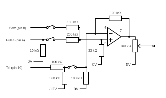
48. Link 24c to 26c
49. 33K resistor 33j to blue
50. 100K resistor 31g to 32g
51. 100K resistor 32j to blue
52. 10K resistor 19b to blue
53. 100K resistor 22h to 26h
54. 560K resistor 26e to 26g
55. 100K resistor 33h to 41h
56. 200K resistor 33g to 45g
57. Pink wire link 32i to 49i
58. Green wire link 26j to 50h
59. Yellow wire link 31ito 37f
60. Brown wire link 42h to 23a
61. Purple wire link 46h to 19c
62. Blue wire link 35f to blue
63. Switch j40, 41j and 42j
64. Switch 44j, 45j and 46j
65. Switch 48j, 49j and 50j
66. 100K potentiometer 35j, 36j and 3j7

Final thoughts on the breadboard voltage controlled oscillator project
To control the pitch of the voltage controlled oscillators connect the control voltage to pin 15 of the AS3340 via a 100K resistor. Use a 1% metal film if you can get one. Connect it between 9h and 4h and the control voltage input can be at 4F. This will enable you to set the pre-set resistor to tune the oscillator to 1V per octave standard.
The breadboard voltage-controlled oscillator output is 36f. The 3 switches select the waveforms and the potentiometer controls the output level.
This project builds a very high-quality voltage-controlled oscillator, especially if you use higher-quality components as mentioned in the text. The CEM3340 IC was used in all sorts of synthesizers built throughout the eighties and it has become widely used in Euro rack modules since it has been reissued along with equivalents.
If you have any problems getting this project to work check out my article “Common Breadboard Mistakes” to help you locate where you might have gone wrong.
The configuration I have used here is similar to that of the Sequential Circuits Pro One synthesizer.
If you want to build a large breadboard project then have a look at my “Breadboard synthesizer project” for full instructions and diagrams to build a CEM based synthesizer similar to the Sequential Circuits Pro 1 synthesizer.

“Hi, I’m Graham Moore and I’ve been building electronic projects since I was 12. I had a fascination for old radios and taking them to pieces but when my Nan bought me an electric soldering iron, I realised with a few components I could build stuff.
Learning to solder opened up many doors for me as electronics also became a career. I hope you get as much from it as i did”.
Breadboard design software

Breadboard design software tested and compared If you use breadboards, you might find breadboard design software helps with your building. Breadboards are tremendously useful for beginners who can’t solder…
Best breadboard kit buyers guide

Best breadboard kit buyers guide In this “Best breadboard kit buyers guide”, I’ll attempt to point you in the direction of the kit that best suits you. Breadboard kits come…
Where to buy breadboards

Where to buy breadboards So if you’ve found this page that means you’ve probably decided you want to buy a solderless breadboard and you want to know where to buy…