

What is GRBL software used for?
GRBL is the motion control software for the Arduino microcontroller board, it is open source and free so it’s often used for CNC machines. It is compatible with Arduino’s that use the ATmega328 and it’s also used on the popular 3018 CNC machines so I presume there is an Atmega 328 somewhere on the boards they use.
If are thinking of buying a 3018 CNC machine I own one and have written an article that you may find useful here.
GRBL has various settings that the user can set, these are stored on the board and not lost when the board is powered down.
GRBL software default settings
When GRBL is first loaded it will contain default settings, you’ll probably need to change them to make your machine work better.
When I first got a 3018 CNC machine I almost gave up on laser engraving because the results I was getting were pretty poor, to say the least. Text and pictures came out as though they were done with a pen that wasn’t lifting off the surface so all the joining lines were engraved as well. I posted on a forum and someone asked “you have enabled laser mode in GRBL, haven’t you?”
I obviously hadn’t as I knew nothing about laser mode in GRBL. Once I enabled it and the results were perfect. I quickly thanked the poster and set about reading up on GRBL.
So what is “laser mode” and what are these GRBL settings?
If you haven’t installed GRBL on your Arduino yet I have some instructions here on how to do it here. If you already have GRBL installed or you have a 3018 CNC machine which already has it you can edit the GRBL settings without too much of a problem but only alter them if you know what they do!
So back to laser mode first make sure you have the latest GRBL 1.1 and change setting $32 = 1
How do you change GRBL settings?
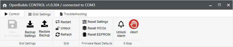
The easiest way to alter the setting is to do it with some other software I have an article here about CNC software which mentions OpenBuilds CONTROL. There are three tabs, click on the second along, GRBL settings. This page makes changing settings a lot easier than the text edit method you may have seen elsewhere as there is an explanation by the side of the number.
It makes it easier particularly the $3 setting for “step direction invert”. Instead of working out the number you need and using trial and error, the settings can be clearly seen and you simply slide the on-screen switch.
Click on the “Save to Firmware” icon which will un-grey if you change any values. You can also backup and restore from this menu which is useful to do.
The direction the stepper motor axis move
You can change the GRBL settings to alter the direction the stepper motors move without having to change the wiring, the setting for this in GRBL is $3=0
| Setting Value | Reverse X | Reverse Y | Reverse Z |
|---|---|---|---|
| 0 | NO | NO | NO |
| 1 | YES | NO | NO |
| 2 | NO | YES | NO |
| 3 | YES | YES | NO |
| 4 | NO | NO | YES |
| 5 | YES | NO | YES |
| 6 | NO | YES | YES |
| 7 | YES | YES | YES |
The table above shows the axis directions and the values so if you have $3 set to zero, which means none of the three X, Y and Z axis are reversed and you find your Z axis is going down when it should be going up, you can set $3=4, which keeps the X and Y stepper motors moving in the same direction and reverses the direction of the Z axis stepper motor.

The picture above shows how easy it is to change the directions the stepper motors move. It’s a lot more straight forward than using the table above to work it all out.
Setting the steps and revolutions
If you read my earlier article on building a hobby CNC machine for home use, you might remember how once I’d built my first CNC machine and got it operating, I noticed how it was engraving smaller images than it should. I tested the movement and when it should have moved 100mm it only moved 50mm.
This was because I hadn’t set the steps settings in GRBL.
These are $100=800.000 X steps
$101=800.000 Y steps
$102=800.000 Z steps
These were the settings I altered on my CNC machine to so it would move the correct distances. These values will be completely different for your machine and you will have to further “improve” on them when you come to accurately calibrate your machine. You may well end up with $100=800.741 for instance. This is covered in the article about calibrating your CNC machine.

The picture above shows the figures for the steps after calibration. You can see this was before the Z axis was calibrated and with laser mode was disabled.
GRBL settings for limit switches
If you’ve put limit switches on your machine they won’t work properly until you’ve enabled them in GRBL. I’ve fitted three hardware limit switches on my CNC machine. I have an article on limit switches here if you want more information and an article on CNC machine homing here as the three subjects are interrelated.
With three hardware limit switches I’ve enabled hard, soft and machine homing by setting
$20=1 soft limits enable
$21=1 hard limits enable
$22=1homing cycle enable

Homing settings direction
If you have fitted three hardware limit switches, you have to set the machine to move in the direction of those switches. If you home the machine and it goes in the wrong direction stop it.
You set the direction with the $23 setting. If you look at the table for which direction the Axis move you can work out what number you have to enter from 0-6. This is the same table and values as for $3 commend which controls the directions the machine moves or step direction.
There are other settings you can change for the homing cycle.
$24=25.000 this is the homing feed rate in mm per minute.
This is the rate the machine moves when it locates the limit switches.
$25=500.000 this is the homing seek rate in mm per minute.
This is the rate the machine moves when “homing” to find the limit switches.
$26=250 this is the homing debounce time in milliseconds.
This is used to minimize switch noise.
$27=2.000 this is the homing pull-off in mm.
This is how far the machine moves away from the limit switches once it has found them so it doesn’t switch them on again.
Setting soft limits
You have to set numerical values for the soft limits for the X, Y and Z values of your machine. This is easy enough to do by moving your machine as for left as you want it to go and reset that value to zero. Then move the machine right as far as you want it to go, look at the value of X for where you currently are and that’s the number to put in your X soft limit. Do the same for Y and Z and then you will have set the correct soft limits for your machine.
$130=222 X maximum travel (mm)
$131=462 Y maximum travel (mm)
$132=70 Z maximum travel (mm)

There are plenty of other settings that you may need to change. The best thing to do is to print off an A4 sheet of the all GRBL settings.
For instance, depending on how you wire limit switches you can invert their action by changing $5=0 to 1.
Same with the Z depth probe, you can invert its behaviour by changing $6=0 to 1.
Other settings cover speeds and accelerations. Bear in mind that these are only the maximum settings that the machine will operate at.
If you use for OpenBuilds CONTROL software to cut material at a feed rate of 300 that’s the speed that it will cut it at, not the rate that is set in GRBL maximum settings. Also the settings here are for my CNC machine and obviously yours could be completely different so hopefully you now understand what you are doing and why and won’t just blindly copy settings.