

Once you’re familiar with how an oscilloscope works, you’ll want to know how to use an oscilloscope. The aim of this tutorial is to show you the best ways of using an oscilloscope if you’re a beginner. The way you use it is going to be dependent on what you actually want it to show you. The best way of doing that is to show a real example of use.
How to use an oscilloscope to fault find
This is a voltage controlled oscillator. Using an oscilloscope you can easily see that it is working and check that everything is functioning correctly.
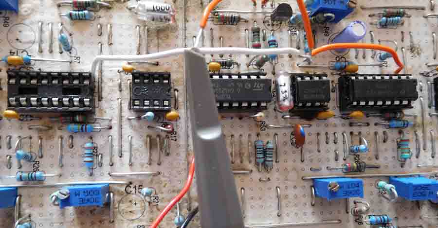
Voltage controlled oscillator board
This voltage controlled oscillator produces four different basic wave forms. Using the oscilloscope it’s easy to check out if these are working. Touching the probes on the various outputs you can actually see the waveforms. This not only shows it’s working but also the frequency of the waveforms. You will also be able to see the output levels. You could check this with an amplifier and hear an audible tone but you wouldn’t be able to see differences in output levels or problems with the shapes of the waveforms.
Spotting the waveform that wasn’t working
When I first assembled the voltage controlled oscillator the triangle wave, ramp wave and square wave were all working but there was no sine wave output. Using the oscilloscope and the circuit diagram you can work your way back and find out what’s going on. The oscilloscope gives you the ability to look inside a circuit. As I could see the other waveforms I knew the oscillator was oscillating and I knew the other waveforms were being produced.
Importantly there was no sign of a sine wave anywhere I touched the probe. I traced it all the way back to the output of the LM13700. Also as you may know the LM13700 is a dual transconductance op amp. Its first half is used in conjunction with a 555 timer as the heart of the oscillator which thanks to our oscilloscope, we know it is working.
Additionally, the second half of the LM13700 is used to take the triangle wave output and produce a sine wave. Subsequently it turned out I had blown half of the LM13700 in experimenting on a breadboard with in in construction. After inserting a new LM13700 a sine wave appeared. This was pretty easy to find where the problem was by using an oscilloscope.
Tweaking the frequency control on the voltage controlled oscillator was also shown to be working as visually on the oscilloscope you can see the waves getting more crammed up or spaced out on the screen. As you increase the oscillator’s frequency the waveform becomes more compact.
As the frequency on the oscillator is reduced the waveform becomes more spaced out. This particular model of oscilloscope also contains a frequency indicator. So you could also use this oscilloscope to calibrate the tuning of the voltage controlled oscillator.
Using a oscilloscope to see pulse width
If you look at the square wave output on the oscilloscopes screen you can also verify that the pulse width control works. If you’re not familiar with voltage controlled oscillators this control allows you to vary the width of the square wave cycle. Again difficult to check without a scope but you can clearly see it working with one.


The pulse width of the square wave being altered from square through to narrow and wide.
You may be able to verify that a project like this is working without a scope but it certainly makes it a hell of a lot easier. There are some things however on this project that I don’t know how else you would be able to get away without one.
Adjusting the ramp wave
The ramp wave function needs you to set a pre-set for the wave to be produced properly. Straight from construction the waveform produced is shown on the picture below. As you can see it’s easier to show than it is to describe it in words.

The ramp wave before adjustment, notice the step in the wave.
You have to adjust the pre-set to get rid of the step. Easy to do with a scope but no idea how you would attempt it without. As you can see below in the picture the correct adjustment has been made and the ramp wave appears as a ramp.
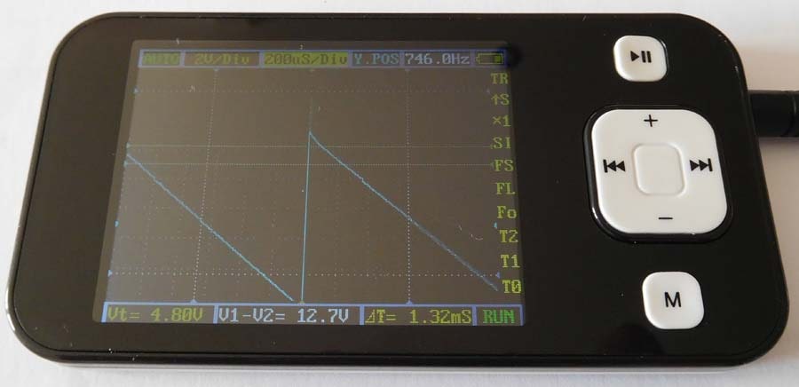
The ramp wave after the correct adjustment.
This particular oscillator also has two pre-sets for the sine wave. One adjusts the roundness of the wave and the other alters the symmetry of it. Once again easy to tweak and observe the oscilloscope screen as you tweak to get the adjustment correct.
Final thoughts on how to use an oscilloscope
As you can see it’s a lot easier to explain exactly how to use an oscilloscope on a real application. There are some things you may be able to do with other bits of equipment but an oscilloscope makes the job a lot easier. There are however things that I have shown you that would be almost impossible to set correctly without an oscilloscope. Hopefully now you know how a scope works and how you use one and you will be a lot more enlightened as to how they can help in electronic fault finding setting up and calibration.
I have reviewed the DSO201 oscilloscope here if you want to find out more about it. I also have an article on the best hobbyist oscilloscopes in my opinion if you are looking to get one. If you have extremely limited budget you might also want to check out my soundcard oscilloscope article where you can build a PC scope.