
[show_wp_shopping_cart]
Having spotted the Shruthi project on the internet I pretty soon decided that I had to build one. The construction looked well within my capabilities and the parts looked readily available. The only things that looked a bit daunting to me were the microcontroller and the memory. Luckily the microcontroller, the ATmega644p was available pre-programmed from Modular Addict, the same place as the PCB’s. So if the worse came to the worst and I was unable to successfully program it, I could buy one. I have previously used PIC’s but not the ATMEGA644p but even if I had I’m not sure I would have been able to build the hex files. I read the instructions but it was far beyond my understanding.
“Run git submodule init and git submodule update to pull the dependencies.”
That’s one of the instructions and I haven’t got a clue what any of it means!
Luckily I managed to find the assembled hex files on the internet so it would hopefully just be a case of learning how to program them.
There are only two PCB’s to assemble and there’s no wiring as all the parts are PCB mounted. The first board you build is the combined filter and power supply board. The instructions on the Mutable Instruments website are worth following as you build and test the power supply part of the board first then the rest of it is assembled.
Best Shruthi filter
There are various types of filter boards to build. I choose the SMR markII which seems quite popular. It’s apparently supposed to sound quite Roland like so that seemed like a good idea, another popular choice is the Polivoks filter from the famous Russian synthesiser, that one is more aggressive with bite apparently.
One thing I noticed is that there are no resistor numbers or values screen printed on the board so you have to work from the website picture for the resistors. Luckily the power supply worked first time with plus and minus five volts showing up in the correct places.
The rest of the construction is straightforward, working you way through the resistors and small capacitors. Be careful with the resistors as it’s easy to misread the 10K and 18K and muddle them up, the only other noteworthy thing to mention is the non-polarised capacitors. These were new to me, normally 4u7F capacitors are electrolytic and polarised however these look similar but don’t have a positive or negative.
Building the Mutable Instruments Shruthi SMR4 mkII filter board
After buildind a Shruthi SMR4 mkII filter board I decided to build another board in a more traditional way of putting in the smallest components first. I find this easier and you can still test the power supply without inserting the IC’s.
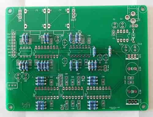
This is the Shruthi SMR4 mkII filter PCB with all of the resistors soldered in place.
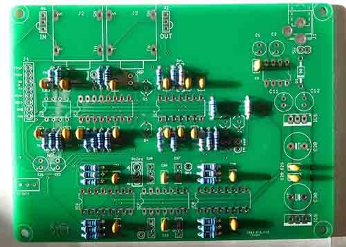
Now with all the small capacitors soldered in.
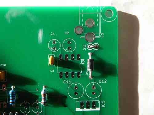
Solder in D1 making sure it’s the correct way round and don’t forget to solder in a wire link at SW if you’re not going to use a switch.
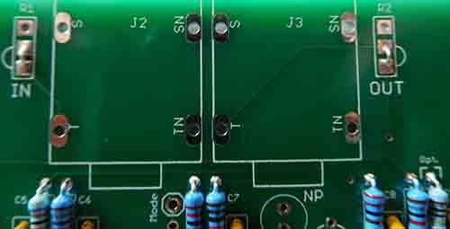
While were talking links solder in the two for in and out.

This is the PCB with the rest of the capacitors fitted.

The 7805 and 7905 regulators soldered in place.
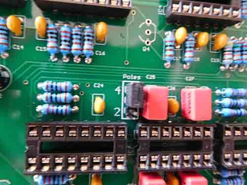
You can just solder a wire link for poles on the filter. I decided to fit a jumper so I could experiment with switching between 2 pole and 4 pole. Don’t forget to actually fit the jumper. it work work at all without it in one of the positions!
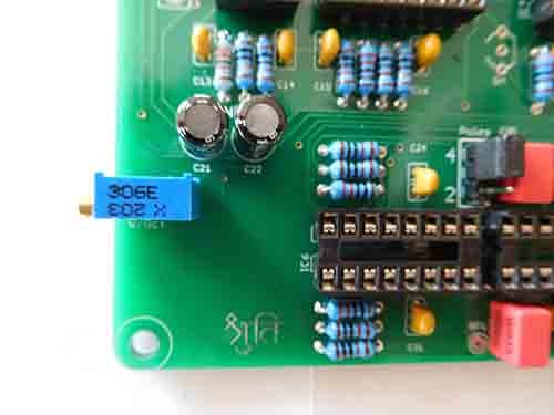
Finally solder in the pre-set, this will enable you to tweak the filter to track 1/V octaves.

Next insert the LT1054 and you can apply power and check that the voltages are correct. Note that C1 is not required to be fitted.
Building the Mutable Instruments Shruthi Control board
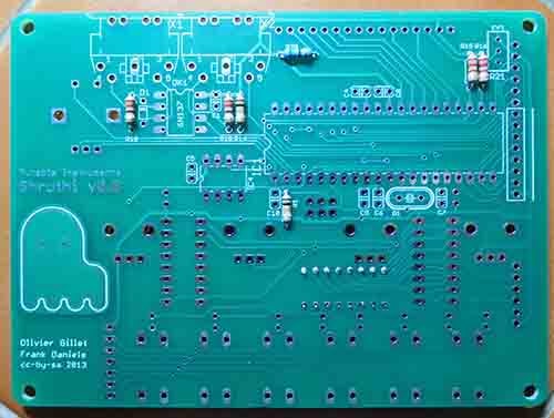
The Shruthi control board with the first 7 resistors soldered in, note that some parts are soldered onto the other side of the PCB. Double check before you solder as they are difficult to desolder!
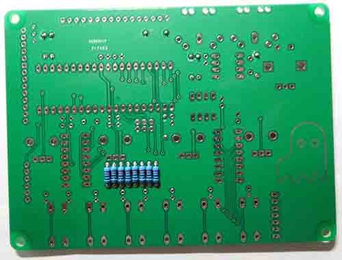
These are the 8 resistors that have to be soldered on the other side.
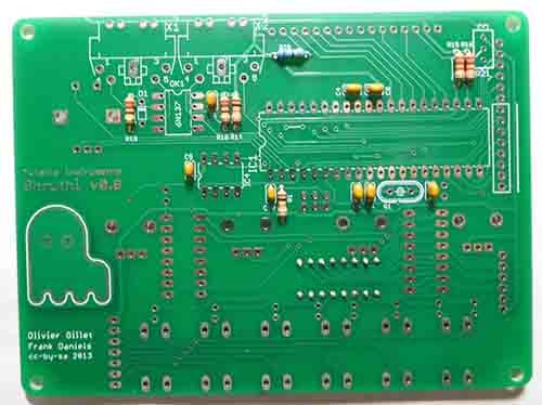
The 8 small capacitors soldered.
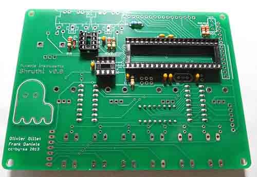
D1 is soldered in place and then the 3 IC sockets.
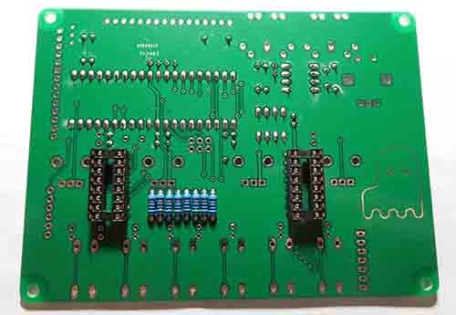
Turn the PCB over and solder in the 2 IC sockets.
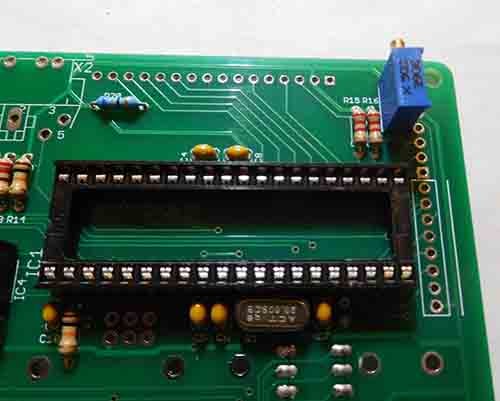
Turn the board over and solder the crystal and pre-set.
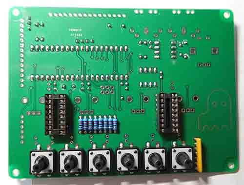
Push buttons and resistor pack.

Solder the MIDI sockets, make sure they are properly seated.

The Shruthi PCB with variable resistors and the encoder soldered in place. Note there are 2 small capacitors to be soldered on this side.
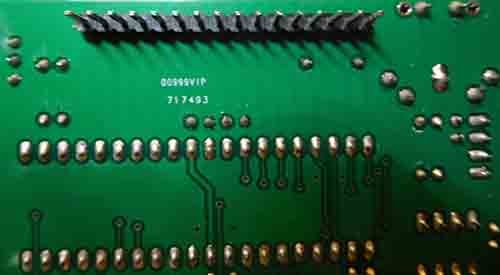
Solder the 16 way display connector in place.

The ISP connector soldered in place.
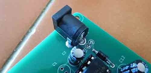
Back to the Shruthi filter board, solder in the PSU socket.
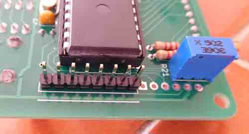
Back to the shruthi control board, solder in the 8 way connector to fit the two PCB’s together.

Next solder main display module, you might need to put a thin piece of card under it as some have metal strips that could short connections underneath it. The LED’s can be soldered in next, make sure they are the correct way round.

Back to the filter board, solder in the connector.
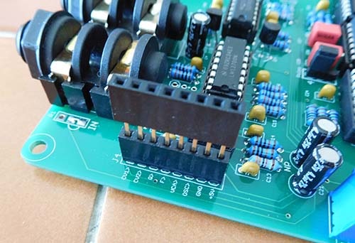
Another connector is then plugged into it to make up the height difference.
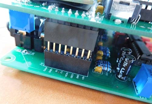
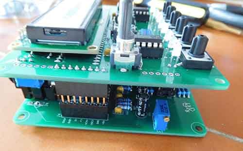
Finally plug the two finished circuit boards together. you’ll need to screw some spacers between the fixing holes to hold everything firmly together.
If you now power it up the main display should glow although no characters will be shown and some of the LED’s should light up.
Programming the Shruthi ATmega644p
All that’s left to do now is program the ATmega644p if yours isn’t pre-programmed. you can plug it directly into a programmer if yours can do that. I decided to do it directly.
ICSP or in circuit serial programming
I bought a Hobby Components USBASP AVR Programmer and Adapter from Amazon to program the ATmega644p as it got good reviews and was a very good price. I had decided to program the ATmega644p in circuit. If you do that you have to make sure that the USBasp isn’t providing power to the chip. It can provide 5V or 3.3V by means of a little jumper J1 on the board. You just have to remove it for ISP programing and not lose it!
The ATmega644p will of course now need to get it’s power from the board so you will have to power the Shruthi up while you program it.
If you use the USBasp with Windows 10 you will need to disable the “feature” in it that stops you installing the driver and then install AVRdude. There are full instructions of how to do this here.
You need to power the Shruthi board with the ATmega644p on it and have installed all the software as shown in the Programming the Atmega644 and the Atmega328 for the Ambika synthesiser article, plug it into your PC and the other end into the 6 pin ISP socket on the Shruthi board.
Shruthi firmware
There are a few different firmware’s available if you search the internet. Some are older versions. You need the Shruthi hex, the boot hex and the internal eeprom hex
Yam Shruthi alternative firmware
There are also other alternative firmware’s that are known as YAM, you will probably find some of these while you are looking for Shruthi firmware’s, check out what is said about them as some are supposed to make the synthesiser better in terms of the sounds of some of the waveforms.
I put the files I’m going to burn in C/Users/(the folder with my name on) and I also rename whichever version of the Shruthi I’m burning to “Shruthi”. That saves me changing any of the lines in CMD.
One tip for you that would have saved me hours, is that if you copy and paste any line from an internet page such as this very one, paste the outcome to a word-processed first and get the word processor to show carriage returns and other symbols that you can’t see. You do it on Microsoft Word with the symbol that looks like a backwards filled in p and a t. if there are any carriage returns in the line remove them as CMD thinks it’s a new line. I copied a line from a web page and CMD kept telling me it didn’t recognise the command as I’d got a “return” from the webpage that I couldn’t see when it was pasted into CMD.
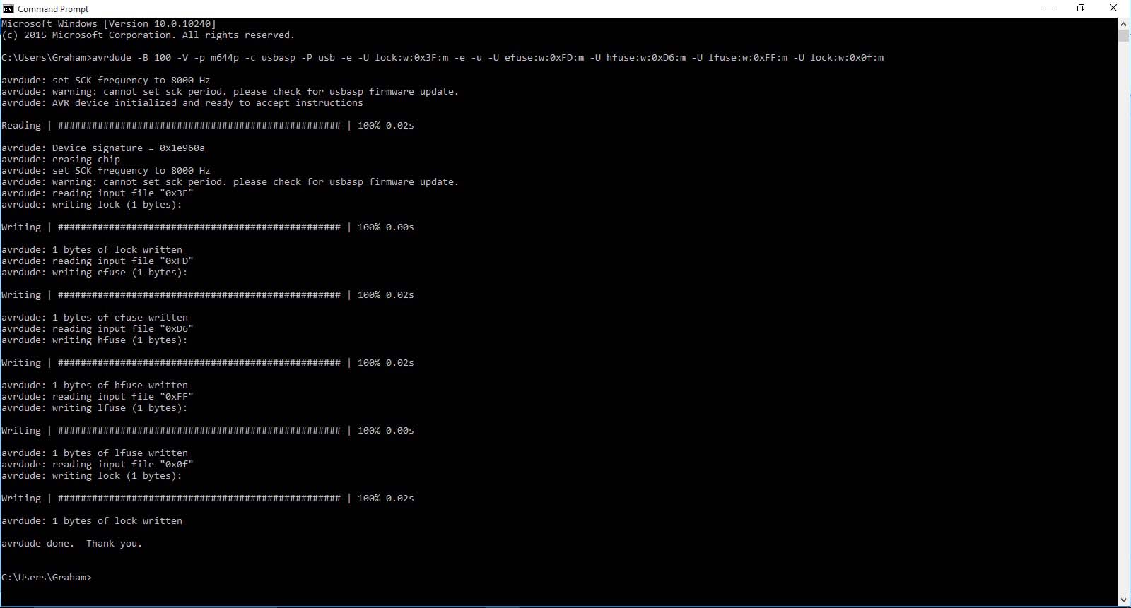
Use the command
avrdude -B 100 -V -p m644p -c usbasp -P usb -e -U lock:w:0x3F:m -e -u -U efuse:w:0xFD:m -U hfuse:w:0xD6:m -U lfuse:w:0xFF:m -U lock:w:0x0f:m
This sets the fuses
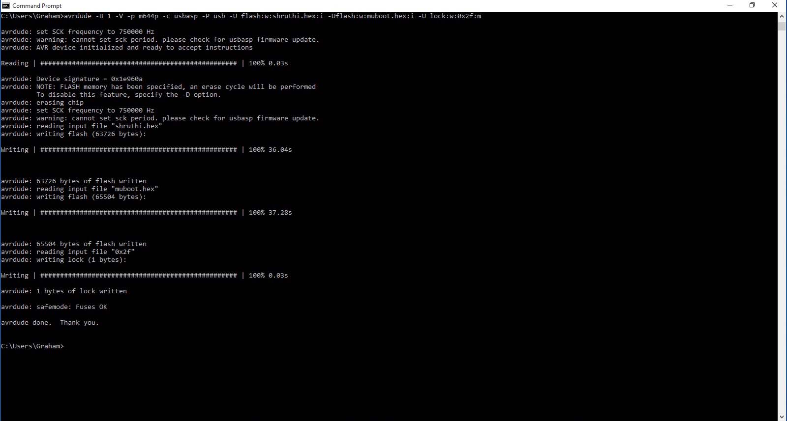
avrdude -B 1 -V -p m644p -c usbasp -P usb -U flash:w:shruthi.hex:i -Uflash:w:muboot.hex:i -U lock:w:0x2f:m
This programs the boot loader and the Shruthi operating system
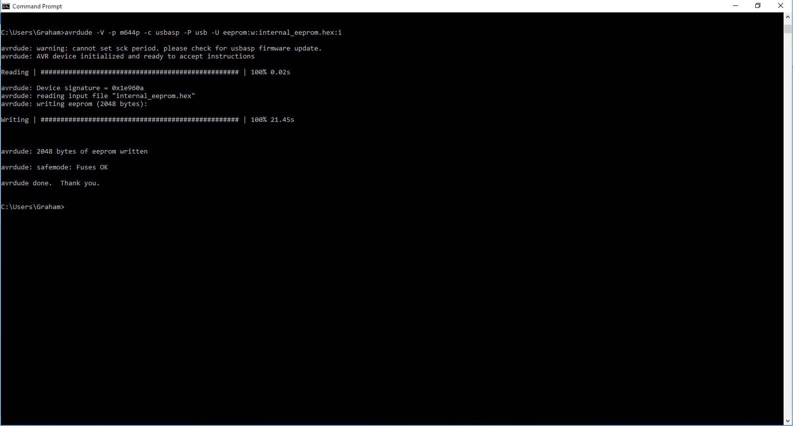
avrdude -V -p m644p -c usbasp -P usb -U eeprom:w:internal_eeprom.hex:i
This programs the first 16 pre-sets.
Once the files have been programmed you should notice that different LED’s are now lit. If you press the switches you should see the LED’s light. You probably won’t be able to read anything on the main display though. Don’t panic if this happens, it’s just that the pre-set needs adjusting on the main control board.
To program the rest of the pre-sets you need a midi interface. Not all of them will work for this application. I used the Behringer U-PHORIA UMC204HD Audio Interface and the MIOS studio software, this has a tools section with a MIDI sys ex transfer tool. You only need one midi connection from the output of the MIDI interface to the input on the Shruthi. Load the Shruthi sys ex data into the MIOS program and then click on play. You don’t have to press anything on the Shruthi. After a few minutes the transfer will finish and the Shruthi will have the pre-sets from 17 onwards installed.
Mistakes building the Mutable Instruments Shruthi
I soldered the 6 pin header for in circuit programming on the wrong side of the PCB, this doesn’t cause any problems until you want to use it. I connected up my USBasp to program the eeprom. This was supposed to come pre-programmed but after I got the Shruthi working there were no pre-sets so I figured it hadn’t been pre-programmed. I then realised after the USBasp wouldn’t communicate with the ATMEGA644p that the header was on the wrong side so the pins were back to front. The 6 pin header isn’t show soldered in the instructions, pretty weak excuse I know. Anyway the picture below shows how it should look.
Once I had de-soldered the 6 pin header and soldered it on the correct side of the board (that’s something that is quick to write but not to actually do! Make sure you get it right first time!)
I am now selling built and tested Mutable Instruments Shruthi Synthesisers.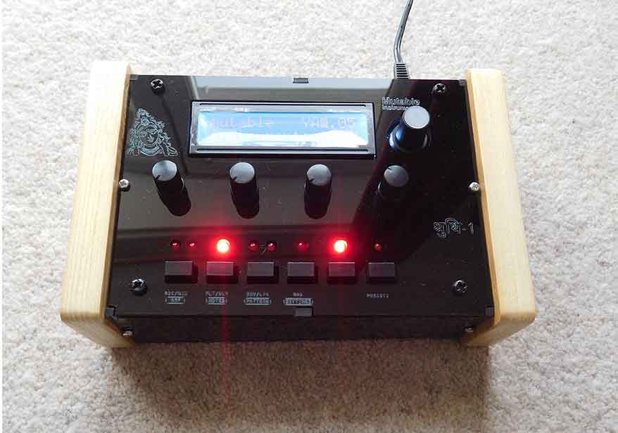

These come cased in a black acrylic case with pine ends. You can purchase with or without a UK mains adapter.
First option is with a 9V adapter and includes free UK mainland postage £160.00
[wp_cart_button name=”Shruthi 1 and mains adapter” price=”160.00″]
Second option is without an adapter but with free UK mainland postage £150.00
[wp_cart_button name=”Shruthi 1″ price=”150.00″]
[show_wp_shopping_cart]
Mutable Instruments Shruthi case also available.
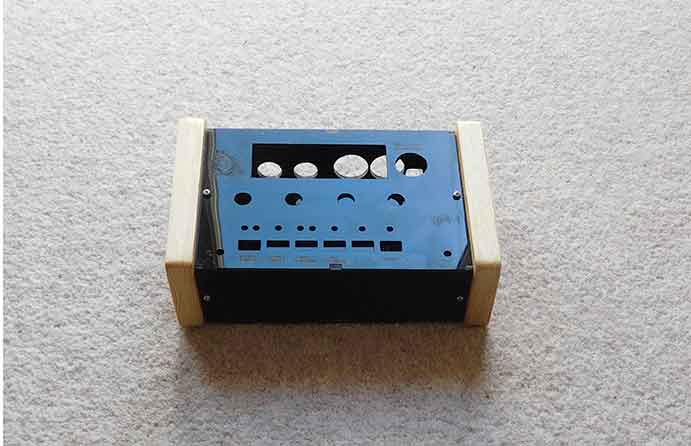
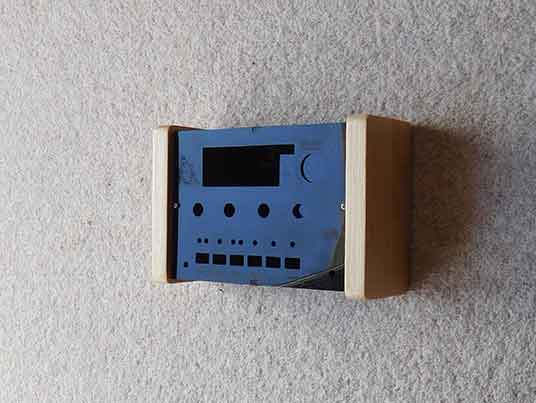
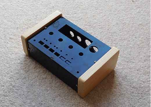

Price includes free UK mainland postage £35.00
[wp_cart_button name=”Shruthi Case” price=”35.00″]
[show_wp_shopping_cart]
If you would like more details or you would like me to quote you for overseas shipping please email me.
email. Grahamdavidmoore@gmail.com
You can download the operating manual for the Mutable Instruments Shruthi 1 from here.
Shruthi XT
There is also a Shruthi XT available. This is sonically the same as the original Shruthi put has more of the controls available on the front panel instead of having to go through the pages to edit them.