

Build a soundcard scope
I recently decided to try and build a soundcard scope after I became aware of some Windows software to turn your PC into an oscilloscope. Furthermore having had a fair bit of experience with oscilloscopes over the years I thought I’d have a look at it.
Once this was completed I started looking at other PC soundcard scope software.
If you’re interested you can read my article on PC oscilloscope software here.
After looking at the software I decided I’d go about building the required hardware to turn a PC into a functioning oscilloscope. You should be aware that this project will only be able to work over the audio range.
Alternatively, if you want a fully functioning PC oscilloscope, you can do this with a USB oscilloscope. For around £70 you can turn your PC or laptop into a 100 MHz bandwidth oscilloscope.
If this is what you’re looking for definitely check out my buyer’s guide here “Best USB oscilloscope review”. This contains some tips and advice to help you make the right choice.
Make your own oscilloscope
Anyway back to the original idea of building an oscilloscope.
Importantly as the probe connects to the soundcard it’s a recipe for disaster connecting straight to it. You’re just asking to blow the input of you soundcard. Even worse if it’s the soundcard in your laptop. You’re going to need something to act as a buffer between the probe and the soundcard input.
I found a circuit on the internet from Timothy Witham which was adapted from a circuit from “The art of electronics”. I’ve adapted the circuit to use parts that I had lying about so it’s not actually cost me anything.
I’ve used an LM351 op amp, the diodes are all 1N4148’s everything else is pretty straightforward. You need a power supply of + and – 12 volts. Connecting the end of R4 to 0 volts switches the probe between X1 and X10.
The buffer should ensure that if you’re going to blow anything. It will be the buffer that blows and you can easily replace anything in this circuit rather than ending up with a blown soundcard.
Build a soundcard oscilloscope PCB layout
At the time I built this buffer I was experimenting with building PCB’s again and I’d just got into using the excellent DesignSpark software so I thought I’d give the software a go at a real application. It’s always a better way to get a feel for its real usefulness. I can report that I found the software to be extremely useful. I would quite happily have paid for it but it’s free. It’s amazing when you look at what it can do compared to the first PCB layout software we used to have at the university which cost about three thousand pounds as I remember.
The buffer circuit was drawn into DesignSpark. You can see it in the picture below.

From the circuit, the program generates a netlist. You can then manually move and position components or let the program have a go. I made the layout single sided because that’s all I can make at the moment, which isn’t a problem considering the simple circuit and came up with the PCB layout shown below.

You can also render a 3D graphical representation of what the assembled board will look like. You can tilt and move it around and turn it over on screen. Much like if you were physically holding the board in your hand. You can look at anything you want. Again this is really impressive and gives you a real feel for what the completed board will be like.

Connect up your soundcard oscilloscope buffer board
I just used a couple of clips instead of an oscilloscope probe while I was experimenting, you can see the completed board in the picture below.
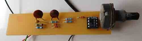
The connections to and from the board that you can see are the thick black cable to the soundcard. The black and red with clips to the circuit on test and the black, red and green, to 0, +12 and -12 volts.
If you can’t make PCB’s this is an easy enough circuit to knock up on a small piece on veroboard. If you’re not too sure about using veroboard I have an article here.
Build a soundcard oscilloscope software
Once the hardware is complete you just need the software. You can read my full article on PC oscilloscope software here or just use what i did in the end.

The above picture shows a screenshot of the soundcard scope buffer circuit running Scope V1.46 connected to an oscillator that I built on veroboard. To be honest I’m amazed at how well it shows the wave form and how smooth it is.
Oscilloscope for audio testing
Obviously this soundcard scope won’t be able to compete with a fully functional oscilloscope.
If you are on the lookout to get a fully functioning digital oscilloscope read my buyer’s guide on the Best hobbyist oscilloscope here. There is a very good model available for only around £140.
Because of the soundcard, you won’t get a very large bandwidth but for basic use on audio circuits, it’s a lot better than having nothing.
Final thoughts to build a soundcard scope
If you’ve never used an oscilloscope but fancied trying one out this is the project for you.
You will be able to learn what an oscilloscope does without having to spend much money at all.
If you are a beginner and you want some information be sure to check out my article “How to use an oscilloscope”. This will give you some real examples and tips.